Using an integrated system to simplify testing of electronic parking brake control systems
January 03, 2017
Electronic parking brake (EPB) control systems are replacing the traditional foot pedal or hand lever, using only a control switch and electrical cabl...
Electronic parking brake (EPB) control systems are replacing the traditional foot pedal or hand lever, using only a control switch and electrical cabling routed to a controller. With the press of a button, the driver can hold their vehicle in place on a slope.
Off-the-shelf test systems designed for testing automotive electronic control units (ECUs) are now available that can be easily configured for functional testing of EPB control systems.
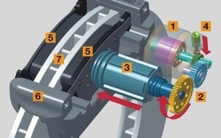
EPB functionality relies on four elements: control switches, a wheel-speed sensor, a force sensor, and electric motors. Together, these monitor a variety of input signals and determine when to apply or release the brakes.
Functional testing of a typical EPB system requires a combination of control, emulation, simulation, and measurement: input/output (I/O) to all test nodes; emulation of analog signals from the force sensor; emulation of frequency signals from the wheel-speed sensor; load switching to the electric motors; and simulation of control switch activity.
Emulating EPB operation
Figure 1 is a simplified block diagram that illustrates the operation of a typical EPB system. Figure 2 shows the emulation capabilities required to test an EPB control module.

[Figure 1 | An EPB system uses closed-loop feedback to determine the correct action.]

[Figure 2 | Functional testing requires emulation of the expected signals and loads the EPB will experience in operation.]
Testing of ECUs requires specific capabilities such as high-power load emulation and generation of multiple signal types that accurately emulate sensor signals. A closer look at each of the essential functions will help define a typical set of test requirements.
Communicating with an ECU
Some form of I/O check is often needed to validate ECU operation. This relies on the ability of the test system to communicate using a suitable serial interface, and the most common of these is the ISO 11898 controller area network bus protocol (i.e., CAN bus). The system must also be able to switch the ECU between “application” and “test” modes.
Simple I/O checks can be easily accomplished by checking for opens and shorts on the assembled connector pins; Input tests can be done by reading the respective ECU states in response to specific analog or digital inputs; Verification of proper output behavior requires measurements of output signals using specific trigger states.
Emulating analog signals
A typical EPB system uses a Hall effect force sensor to measure clamping force. The actuator uses closed-loop control, relying on feedback from the sensor to determine how much force is needed to hold the vehicle in place. This is accomplished by controlling the amount of torque that is applied to the brake pads through an electric motor.
Depending on the sensor type, typical voltages range from 0 V to 5 V. Functional testing and product characterization require the ability to produce either a range of discrete voltages or a sweep of voltage levels that will drive the EPB, in its test mode, through the full range of possible states. The emulated static signal is applied to the force-sensor input pin.
Producing frequency signals
The wheel-speed sensor provides an output that is directly proportional to the rotational velocity of the wheels on the vehicle. The resulting signal is a current pulse wave that typically ranges from 7 mA to 14 mA in amplitude and from 10 Hz to a few kHz in frequency.
In testing, a frequency generator is used to emulate the sensor signal into the EPB receiver. Similar to the analog testing described above, functional testing requires the application of either a set of discrete frequencies or a frequency sweep to the input of the EPB.
Managing and simulating loads
In the EPB system, activation and deactivation of the brakes requires an actuator that works with the electric motor. When the motor is powered on, it rotates and actuates gears that apply force to the rear brakes and immobilize the vehicle. To release the brakes, the motor rotation is reversed and the force is removed.
To drive the electric motor with sufficient torque, the EPB must deliver relatively high power levels. As a result, the functional test system must include a signal-switching system capable of handling high current levels (10 A to 20 A) while also providing flexible connection and disconnection of the simulated loads.
Outlining the solution
In the past, automotive manufacturers often had to create their own rack-and-stack test systems. In addition, they sometimes incurred the time and expense of developing custom electronic circuitry and system control software.
Today, an off-the-shelf alternative uses PXI-based hardware and commercial test executive software as the foundation of an EPB-specific solution. One such solution from Keysight Technologies, Inc. uses an embedded PC controller and seven hardware elements that provide the required functionality:
- Digital multimeter (DMM)
- Dynamic digital-to-analog converter (DAC)
- Digital I/O (DIO)
- Pin-matrix cards
- Load-switching cards
- CAN bus communication card
- Programmable power supply
These fit into a one-box tester, with the programmable power supply mounted above a pair of card cages (Figure 3). Using a modular form factor gives test engineers the flexibility to mix and match the test and measurement hardware needed to address a wide range of requirements. In addition, the system’s compact size simplifies integration and reduces rack space.

[Figure 3 | This configuration of the Keysight TS-8989 PXI functional test system includes a programmable power supply (top), an eight-slot PXI chassis (lower left), and an 11-slot switch/load unit (lower right).]
The system includes test executive software designed specifically for the development and execution of electronic functional testing. It includes a fully customizable user interface, an open architecture for multiple-instrument integration, flexible test sequencing, and easy-to-use debugging tools. Its reusable library contains functions such as instrument handlers, test actions, and test sequences. Capabilities such as a switch manager, state-based switching, a test profiler, and a throughput multiplier boost productivity and accelerate test speed.
Meeting EPB test requirements
For voltage and resistance measurements during I/O testing, the system can be configured with one of two 6½-digit DMMs, providing 4,500 or 15,000 readings per second, respectively. Basic accuracy for DC voltage is as high as 90 ppm. To simplify measurement set up, the test executive includes high-level actions for measurements of DC voltage and two- or four-wire resistance.
The EPB is connected to the DMM and signal sources through a choice of pin-matrix cards available with a mix of instrument and measurement channels. Switching speed is as fast as 300 µs, and the long-lasting switches are rated for up to 100 million operation cycles. The test executive provides a switch-path editing tool that streamlines matrix programming.
To create the analog signals needed during force-sensor testing, the system can be configured with a PXI dynamic DAC. The test executive includes a variety of commands that simplify configuration and triggering of the DAC output.
The dynamic DAC is also used to generate the frequency signals needed to test the wheel-speed sensor. The DAC has a 500 kSa/s update rate and can produce symmetrical and asymmetrical current-pulse signals. Using one module to support both voltage and frequency testing reduces the cost of the system compared to those that require two separate sources.
To automate load switching and motor testing, the system can be configured with single-, dual-, or quad-load cards. For load switching, the system can handle currents from 2 A to 40 A depending on the chosen load card, enabling current sensing, flyback protection, pull-up/pull-down loads, bridge loads, and multiplexed loads.
Flexible off-the-shelf functional testing for next-gen automotive
Every advantage counts in today’s increasingly competitive automotive industry. On-time and on-budget deployment of an EPB functional test system benefits from off-the-shelf systems that are capable, flexible, and customizable. Using a single, integrated PXI-based system that includes measurements, switching, and loads gives manufacturers a cost-effective solution for EPB testing. By saving rack and floor space, this compact configuration also helps reduce the overall cost of functional testing.
Keysight Technologies, Inc. www.keysight.com/find/automotive.
LinkedIn: www.linkedin.com/company/keysight-technologies
Facebook: www.facebook.com/Keysight
Google+: plus.google.com/116913596722042872358/posts
YouTube: www.youtube.com/user/keysight