
Using a memory protection unit with an RTOS, part 3
May 25, 2018
Story
This installment looks at how a process can communicate with another process and what happens when a process attempts to access a memory location or a peripheral device outside its allocated space.
This is part three of a four-part series. Read the other three parts here: Part 1, Part 2, and Part 4.
So far, we looked at what an MPU is and how it can help isolate tasks and processes from one another. We’ve also examined how to set up the Cortex-M MPU and found that it was quite easy to use. The complexity of using an MPU has more to do with organizing the memory of an application than the mechanics of updating this highly useful device.
In this installment of this series on using an RTOS with an MPU, we’ll look at how a process can communicate with another process and what happens when a process attempts to access a memory location or a peripheral device outside its allocated space.
Inter-process communication
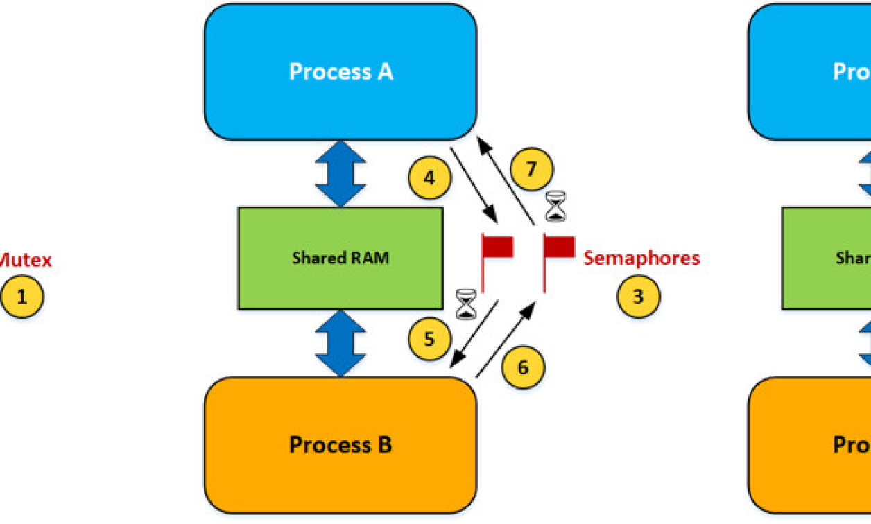
Figure 1 shows different ways that processes can communicate with each other. These are just some of the possible scenarios, and in fact, an application can have a combination of the techniques described below. The Cortex-M also has special instructions to allow lock-free data structures, making shared access simple and efficient, but assumes non-blocking.

[Figure 1 | Inter-process communication.]
Fig1(1) A mutex is used to ensure that two processes do not access the same data at the same time. You should note that the mutex actually resides in RTOS memory space, and through RTOS APIs, the mutex is accessible to either process. Of course, there could be multiple mutexes, each providing access to different resources shared by two (or more) processes.
Fig1(2) Tasks needing access to a shared resource guarded by the mutex must first acquire the mutex. Once the task is done accessing the shared resource, the mutex is released. The hourglass represents an optional timeout in case a task is not willing to wait forever for the mutex to be released by its current owner.
Fig1(3) Semaphores can also be used by processes to signal each other about data availability.
Fig1(4) A task within Process A deposits data into an agreed-upon area in the shared RAM and then signals the semaphore on the left.
Fig1(5) A task within Process B waits for the signal from Process A through the semaphore. A signal indicates that data is available. Again, the hourglass represents an optional timeout to avoid waiting forever for a signal. If the signal doesn’t occur within the timeout period, the task would be resumed by the RTOS. In this case, however, the task will know there hasn’t been anything deposited in the shared area.
Fig1(6) Process B can acknowledge the fact that it processed the data (if a timeout didn’t occur).
Fig1(7) After signaling the semaphore, Process A waits for an acknowledgement with an optional timeout.
Fig1(8) Alternatively, communication can use an RTOS’s message queue mechanism. In this case, a buffer from dynamically allocated memory is obtained from the shared RAM area; the buffer needs to be accessible by both processes. The sender task in Process A fills the buffer and sends a pointer to a task in Process B.
Fig1(9) Similar to the semaphore case, the task in Process B can wait for a reply and specify an optional timeout.
Handling faults
As previously mentioned, the job of the MPU is to ensure that tasks within processes only access memory or peripheral devices that are assigned to them. But, what if these tasks attempt to access data outside of those regions? The answer is that the MPU triggers a CPU exception called the Memory Manage (a.k.a. MemManage) Fault.
What happens when a fault is detected greatly depends on the application and is probably one of the more difficult things to determine. Needless to say, these types of faults should be detected and corrected during development. However, one of the reasons to use the MPU is to protect against those cases where an invalid memory or peripheral access occurs in the field, either because of some corner case that was not caught during system verification or through some unauthorized access.
The MemManage fault is generally handled by the RTOS. Ideally, your embedded system has some mechanism to record and report back faults to developers so corrections (if needed) can be included in the next release. A file system is a good place to record these faults, assuming of course that it can still be relied upon by the fault handler.
When a fault occurs, the fault handler could perform the following sequence of operations (shown as pseudo-code):
void OS_MPU_FaultHandler (void)
{
// Terminate the offending task/process (1)
// Release resources owned by the task/process (2)
// Run a user provided ‘callback’ (based on the offending task) (3)
// If we have a file system: (4)
// Store information about the cause
// Do we restart the task/process? (5)
// Yes, Restart the task/process
// Alert a user (6)
// No, Reset the system (7)
}
- The system designer needs to determine what to do when a fault occurs. At a minimum, the offending task must be terminated, but do we also need to terminate the other tasks in the process? There might not be a single answer, and in fact, it could depend on which task caused the fault. As a result, the MPU fault handler should be designed to perform different operations based on the task or process that triggered it.
- The offending task (or process) being terminated might own resources (kernel objects, buffers, I/Os, etc.) that would need to be released to avoid affecting other tasks/processes. The RTOS is aware of some of these resources and could automatically release them.
- The task that caused the fault might be controlling actuators or other types of outputs that should be placed in a safe state to avoid harm to people or assets. A user-defined callback should be provided by the embedded system designers to take care of system specific actions. The callback is stored in the task’s control block (TCB) during task creation. To improve system safety and security, tasks should be created only during startup while the CPU is in privileged mode, and tasks should never be deleted at run-time unless because of a fault. Since the TCB resides in RTOS space, the callback would not be accessible from user code, thus preventing potentially unsafe and unsecure code from invoking the callback, either unintentionally or maliciously.
- If the embedded system has some form of data storage capability, you might want to log information about the fault: what was the offending task, the value of CPU registers, what action was taken, etc.
- Depending on the task that caused the fault, the task could simply be restarted, and the system can thus recover from this situation.
- If the system was able to recover and if the system contains a display, it might be useful to alert an operation. Also, if the system has network connectivity, then notifying the service department and preferable the development team could help to avoid the issue in future releases.
- If the system cannot recover then, there might be no other choices than to reset the system.
The MPU process table can be altered to include a per-task callback that would be called from OS_MPU_FaultHandler(). Of course, if all the tasks need to perform the same operation upon a fault, then you can either not use this feature or have the callback for all the MPU process tables point to the same callback. I believe the latter option is the most flexible and would be my preferred choice as a system designer as it offers greater flexibility for future releases. That being said, you will probably need to consult your RTOS provider to determine if this feature is available.
typedef struct
{
ARM_MPU_Region_t MPU_Tbl[8][2]; // RBAR and RASR entries
void (*FaultCallback)(..); // NULL pointer if no callback
} OS_MPU_PROCESS_TBL;
References
- Jean J. Labrosse. "Detecting Stack Overflows". https://www.micrium.com/detecting-stack-overflows-part-1-of-2/, https://www.micrium.com/detecting-stack-overflows-part-2-of-2/.
- Wikipedia, “Return-to-libc attacks”. https://en.wikipedia.org/wiki/Return-to-libc_attack.


