
Solving the point-of-load power-design challenges of programmable logic controllers
October 24, 2018
Story

A programmable logic controller (PLC) is an industrial computing system. It controls manufacturing processes on assembly lines and other factory automation equipment for control methods.
A programmable logic controller (PLC) is an industrial computing system. It controls manufacturing processes on assembly lines and other factory automation equipment that require a highly reliable control method and fault diagnosis. A PLC system comprises analog and digital input and output modules, a communication module, a central processing unit (CPU) module, a control module, and a power supply. PLCs operate in harsh, rugged manufacturing environments and require special attention when designing a nonisolated point-of-load power solution. Designers must consider the point-of-load bus architecture, line voltage transients, thermal limitations, isolation noise issues, size constraints, and processor voltage accuracy concerns.
Point-of-load architecture considerations
PLCs benefit from a DC/DC point-of-load power solution that supports the needs of advanced analog and digital integrated circuits, offers high efficiency with good thermal performance, and reduces overall component count and cost. Point-of-load strategies can vary, but PLCs usually have a 24VDC (or occasionally a 12VDC) input from the power supply. The line voltage is susceptible to input voltage transients that originate from motors or relays, however, causing excessive voltage spikes that can damage the system.
In almost all cases, 5V and 3.3V rails are used as secondary regulation rails from the 24V or 12V source to power low-voltage subsystems. It is difficult to regulate a 1V rail with a 24V input while switching at frequencies higher than 1MHz and yet still maintain a small form factor. As shown in Equation 1, to regulate 1V from a 24V input (with a 4.2% duty cycle), the minimum controllable on-time of the DC/DC converter must be lower than 40ns when switching at 1MHz to avoid noisy pulse skipping.
minimum controllable on-time = duty cycle / switching frequency (1)
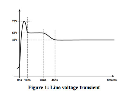
Line voltage transients
Line voltage transients can come from motors and relays in the system and cause an excessive voltage spike on the input voltage line. Since PLCs are employed on factory floors that may have motors or other inductive loads and loops, they are susceptible to line transient spikes. Figure 1 shows an example of a line voltage transient that may have a short duration, but can severely damage circuits inside PLCs without proper protection.
A protection or clamping circuit (shown in Figure 2) can protect the load from voltage spikes. Diode D2 sets the clamp voltage, and a pass field-effect transistor (FET) enables the current to flow to the load protected. Unfortunately, these circuits take up space and require additional components. Implementing an e-fuse, such as the TPS2660 family, also provides protection up to 60V, and is much easier to implement than the discrete circuit in figure 2. An e-fuse can also provide input reverse voltage protection that a DC/DC converter does not usually provide. Non-isolated synchronous buck converters with integrated FETs are available with ratings up to 100V to protect downstream circuits as well.

Thermal limitations and power budgets
PLCs are often enclosed in cabinets, where the airflow is either constricted or unavailable. In many cases, it’s not possible to use a cooling fan because of the presence of dust, corrosive elements or other material limitations. System long-term reliability degrades under excessive thermal stress.
Thus, reducing the power dissipation of a point-of-load power solution will increase the power budget of a module and allow the PLC to be distinct in the marketplace. Additional available power also enables faster microprocessor clocking speeds, more accurate data converters and additional memory to improve performance against the competition.
Operating a DC/DC converter at peak efficiency is an excellent way to minimize the conduction and switching losses of the DC/DC converter’s power metal-oxide semiconductor FETs (MOSFETs). Table 1 shows the efficiency of a 2A converter design de-rated to 0.5A compared to a 0.5A converter using WEBENCH Power Designer. Obviously, the smaller MOSFETs of the 0.5A converter enable a smaller package size, and the higher frequency enables the use of smaller passive components for a smaller solution size. But the 2A converter saves 140mW of energy when used at 0.5A, maximizing efficiency and improving thermal performance in applications that have limited airflow or constrained power budgets.
|
Device |
Rating |
η (at 0.5A) |
Pd (W) |
Rds(on) |
Frequency |
Solution size |
|
TPS54218 |
2A |
87% |
0.13 |
20m?/20m? |
1.125MHz |
122mm2 |
|
TPS62231 |
0.5A |
80% |
0.27 |
600m?/350m? |
3MHz |
23mm2 |
Table 1: 5Vinput, 1.8V output, 0.5A comparison
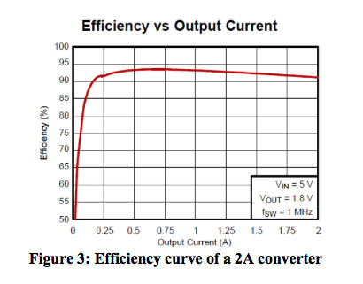
Figure 3 shows how to further optimize the efficiency of the 2A converter. Peak efficiency is about 93% around 0.5A at the knee of the curve, which represents the optimal point between switching and conduction losses.
Isolation to improve electrical noise immunity
PLCs use data-transmission systems such as RS-485, but other communication protocols are also possible, such as Profibus, Profinet or Ethernet. A remotely located power source can experience large ground-potential differences due to multiple, nonstandardized grounding techniques, which cause multiple ground paths and loops. Ground loop currents can be extremely high, because they connect different ground potentials through low-impedance wiring.
Breaking ground loops through galvanic isolation not only prevents loop currents, but is the most reliable method to solve high ground-potential differences. Galvanic isolation allows the input, which is referenced to ground from the input side, to be independent from the ground at the output side, which significantly enhances common-mode rejection and improves noise performance. It is important to have an area on the circuit board that is “isolated” from potentially noisy grounds, and the most popular technique is to implement a 5V input to a 5V output through an isolation barrier.
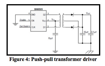
There are several ways to create an isolation barrier using a transformer. The push-pull transformer driver shown in Figure 4 operates at a 50% duty cycle, so the transformer coil must be designed accordingly to accommodate a specific input and output voltage. The push-pull circuit also runs open loop, so there is no feedback mechanism. In some cases, a linear regulator on the secondary side will provide better output-voltage regulation.
The fly-buck regulator shown in Figure 5, also known as an asymmetrical half bridge, has the same transfer function as a standard buck regulator but uses a transformer like a flyback converter. The inductor-capacitor of the buck regulator uses C1 for the output bulk capacitor and the primary side of the isolated transformer, T1. The output voltage is reflected to the secondary side and is derived from the turns ratio of the transformer. R1 and R2 set the duty cycle of the half bridge, which enables more flexibility in choosing an off-the-shelf transformer turns ratio to accommodate the input and output voltages.
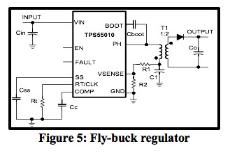
The fly-buck’s frequency is adjustable with the RT pin and synchronizable to a wide range of switching frequencies. The fly-buck is limited to about 2W, since high currents flowing through the diode on the secondary side can limit regulation due to losses. Neither topology requires optocouplers. The fly-buck incorporates primary-side feedback to enable flexibility with the magnetics. For higher efficiency, more output current and better regulation accuracy, the fly-buck converter is a better alternative than the push-pull transformer driver shown in Figure 4.
Voltage regulation accuracy
As process technology advances, field-programmable gate arrays (FPGAs), microcontrollers and application-specific integrated circuits (ASICs) require tighter voltage accuracy and lower operating voltages for their core rails. The processor’s data sheet may specify the voltage tolerance as a percentage or as a value in millivolts, which includes DC, AC and ripple variations over the entire operating temperature range. Designers must also consider the tolerance of the resistor divider used by the DC/DC converter; the routing and trace losses of the circuit board; and variations of the application, like the input voltage variations, temperature swings and fast load changes. These factors all contribute to DC/DC converter accuracy. Many designers will want headroom or margin to make sure that the solution is always within the tolerance expectations of the processor. New advanced processors require a core voltage tolerance within +/- 3% over all conditions, which require the DC/DC converter to have a very accurate reference voltage.
It is important to check the initial feedback voltage accuracy of the DC/DC converter in the data sheet. Table 2 shows the regulated feedback voltage specification of the TPS54218, which is a 2A converter with a reference accuracy ±8mV or ±1% over input voltage and temperature variations. Choosing tighter-tolerance resistors improves the total output voltage accuracy. For more headroom, choose 0.1% or 0.5% resistors [1], even though they may cost a little bit more. With the additional headroom, it will be possible to meet the total ±3% or ±5% output-voltage variation with less bulk and bypass capacitance.
|
Parameter |
Test condition |
Minimum |
Typical |
Maximum |
Unit |
|
Voltage reference |
2.95V ≤ VVIN ≤ 6V, -40°C |
795 |
803 |
811 |
mV |
Table 2: Feedback voltage regulation as shown in the TPS54218 data sheet
Place the DC/DC converter as close to the load as possible. Layout constraints, connectors and board density requirements can interfere with the voltage accuracy to the load. A DC/DC converter with remote sensing can help compensate for a large voltage drop from the DC/DC converter to the load.
Solution size
To keep the total DC/DC converter solution small, either integrate or optimize any external components. Nonisolated power modules have become more popular because of their high level of integration and ease of use, as well as their ability to optimize the inductor to occupy less space. Power modules are usually designed to achieve a smaller total solution size compared to a discrete solution. When saving board space is more critical than total system efficiency, a power module with a high switching frequency may be a better choice than a discrete solution.
Table 3 compares a discrete and module point-of-load solution using WEBENCH Power Designer to calculate solution size and cost under the same operating conditions. The power module occupies less than one-half the board area of a discrete solution, but only adding about 25% of the total solution cost, which is $0.45 in this case. Justifying the use of a module depends on the importance of saving space, and may even be economical at lower production volumes.
|
Device |
Type |
Input voltage |
Output voltage |
Output current |
Solution size |
Solution cost |
|
TPS62130 |
Discrete |
10.8V-13.2V |
1.8V |
3A |
105mm2 |
$1.71 |
|
TPS82130 |
Module |
10.8V-13.2V |
1.8V |
3A |
49mm2 |
$2.16 |
Table 3: Discrete versus module solution comparison
Summary
PLCs operate in harsh, rugged manufacturing environments and require special attention when designing a point-of-load power solution. Challenges such as line voltage transients, ground loop currents, thermal budgets and powering processors are easily manageable when creating a high-performance and reliable product.
Additional Resources:
- Watch the video, “Power protection requirements and solutions for 24-V and 48-V industrial solutions”
- Download the Small, Efficient Power Supply Reference Design for Altera™ MAX® 10 FPGA for up to 125°C.
- Read the application note about Industrial data-acquisition interfaces with digital isolators.
References
- Nowakowski, Richard and King, Brian. “Challenges of designing high-frequency, high-input-voltage DC/DC converters.” Texas Instruments Analog Design Journal SLYT415, April 2011.
- Raj, Arvind. “Calculating Efficiency.” Texas Instruments application report SLVA390, February 2010.


