
Resolving power issues in smart charging automotive systems
August 31, 2017

Reducing CO2 emissions is now mandatory for car suppliers. Considering CO2 is the main greenhouse gas[1], governments set CO2 emission reduction targets for new cars and levy fines on car suppliers on excess amounts of CO2. Automatically stopping and restarting the internal combustion engine is one of the most efficient methodologies to reduce CO2 emissions.
Implementing a start-stop system, however, introduces several problems for car electronic equipment (E/E) manufacturers. The alternator is a power generator mounted under the hood, and it supplies power to E/Es and charges the lead battery. As the alternator is driven by a combustion engine, E/Es in a stop-start experience power usage restrictions and a temporary voltage drop.
Power usage restrictions arise when the engine stops working at a traffic light as the alternator stops too. Hence the power consumption of E/Es is severely restricted as they are sourced only by the lead battery.
A temporary voltage drop occurs when the engine starts working again. The alternator starts working again as well. Since the alternator draws significant current from the lead battery when starting, E/Es suffer from a temporary voltage drop – the voltage typically drops down to 6 V when restarting at traffic lights. The most sever droppage (called cold-cranking, which can drop as low as 3 V) takes place when engine oil is thick because of cold weather.
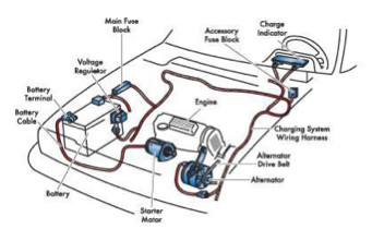
Figure 1. A typical implementation of an automotive smart charging subsystem.
In order to address these two problems, E/E designers conventionally implement solutions that themselves introduce other problems. For example, original equipment manufacturers (OEMs) can restrict E/E operation to save power by turning off some E/Es when the alternator is off. However, this means the loss of some functionality, and may not be comfortable for drivers. When the engine control unit (ECU) finds that battery is not charged enough, it does not turn off the engine to keep the alternator on, resulting in increased CO2 emissions. OEMs also have the option of installing bulky and costly components to endure the voltage drop. For example, a low-pass filter is conventionally installed to sustain the supply voltage during restarts, but the filter is usually large and costly.
An alternative to these traditional approaches is to use a buck-boost switching mode power management IC such as the Cypress S6BP202A. A buck-boost approach generates power rails from the dropped battery voltage. Thus, the power management IC (PMIC) is able to generate a 5 V power rail even when the battery voltage has dropped as low as 2.5 V, without the need for bulky and costly low-pass filters (Figure 2). Consequently, the engine and the alternator can be turned off more frequently, resulting in reduced CO2 emissions. As the PMIC consumes little power (20 μA) for itself (Figure 3), it allows more E/E-based work within the restricted power capacity.
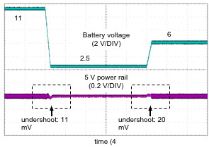
Figure 2. Buck-boost switching mode PMICs can sustain a 5 V rail even when battery voltage is as low as 2.5 V.
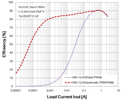
Figure 3. Buck-boost switching mode power management ICs consume as little as 20 μA.
In the past, buck-boost switching mode power systems have not been used in automotive applications. However, advances in buck-boost technology developed for consumer applications have opened the door for automotive applications. Seamless switching techniques suppress voltage variations in state changes from buck mode to boost mode, and from boost mode to buck mode. A drive towards power efficiency has led to low quiescent current. Integrated accurate voltage supervisors improve system reliability, and operation at 2 MHz switching frequency ensures the subsystem does not interfere with AM radio. Finally, factory-preset voltages decrease the risk of voltage variation caused by contamination and/or condensation.
To conclude this article, consider a typical mid-range instrument cluster (Figure 4) that comprises several gauges (e.g., speedometer, tachometer, etc.), a segment LCD (e.g.., trip meter), a beeper, some telltales, and communication interfaces (e.g., CAN). The instrument cluster equips an S6BP202A as a PMIC and S6J3120 microcontroller (MCU).
Though the battery voltage may vary from + 2.5 V to + 42 V, and though the car may experience arctic weather (-40 °C) or scorching heat (+125 °C), the S6BP202A keeps generating a stable +5 V power rail for the S6J3120 under all conditions.

Figure 4. Typical mid-low cluster system
About the Authors:
Leona Okamura is a senior analog product marketing engineer at Cypress Semiconductor. After a two-year experience of circuit design, he is responsible for determining specifications for new products. He has an M.S. in electrical engineering from Waseda University and a B.E. in engineering from Kyoto University.
Yukinori Maekawa is a senior analog product application engineer at Cypress Semiconductor. He is responsible for technical customer support, and has provided know-hows for the power system design for 14 years after a ten-year experience of hybrid IC design.
[1] Greenhouse gas or GHG is a collective term of gases that cause global warming. GHG comprises Water vapor (H2O), Carbon dioxide (CO2), Methane (CH4), Nitrous oxide (N2O), Ozone (O3) and Chlorofluorocarbons (CFCs).


