
COM-HPC Connectors Increase Speed and Density
November 24, 2020
Blog

So, how do COM-HPC connectors enable 2,088 Gpbs/in2? To answer that question, we have to understand the basic design features of COM-HPC connectors and how they contribute to that metric.
2,088 Gbps/in2. That is a unique metric that may not mean much at first glance, but means the world to the edge computing industry.
Next-generation embedded applications, from medical imaging and AI to 5G and edge computing, demand high-speed performance. Scalability and density are a must. The soon-to-be-released PICMG COM-HPC specification targets next-generation, high-performance computer-on-modules (COMs) for such applications.
COM-HPC is a natural extension of the existing COM Express standard, which has been a cornerstone form factor for embedded computing applications for more than 15 years. But while COM Express solutions are still popular and timely, the use cases mentioned previously are pushing the limits of their performance.
That’s where COM-HPC comes in. The COM-HPC specification defines connectors that support high-speed PCIe 5.0 and 100 GbE protocols, while increasing system density using two 400-pin multi-row interconnects.
So, how do COM-HPC connectors enable 2,088 Gpbs/in2? To answer that question, we have to understand the basic design features of COM-HPC connectors and how they contribute to that metric.
COM-HPC Connectors: The Basics
The COM-HPC specification offers system and interface flexibility by adopting a pair of 400-pin connectors (800 pins total) based on Samtec’s AcceleRate HP High-Performance Arrays. AcceleRate HP is an incredibly dense board-to-board interconnect system with high pin counts, a compact footprint, and low-profile stack heights (Figure 1).
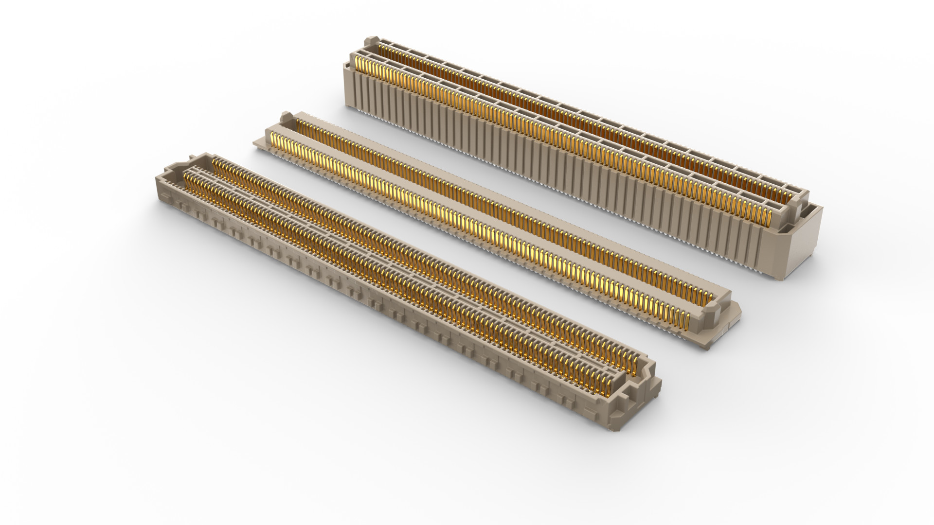
COM-HPC connectors feature a flexible, open-pin-field array. This unique design provides maximum grounding and routing flexibility by allowing system architects to route high-performance differential pairs, single-ended referential signals, and power via the same interconnect. The inherent routing flexibility of COM-HPC connectors enables the different COM-HPC Server and COM-HPC Client pinouts.
COM-HPC connectors offer 400 pins in a four-row, hundred-pin-per-column configuration. This nearly doubles the pin count from COM Express. With a small 0.635 mm pitch, the COM-HPC connectors feature an ultra-micro footprint compared to COM Express solutions.
The connectors’ female Module Receptables are employed at a standard height. The male Carrier Plugs vary to allow for either a 5 mm or 10 mm stack height. COM-HPC connectors also utilize industry-standard ball grid array (BGA) termination, which simplifies the assembly process by leveraging standard surface-mount technology (SMT) manufacturing techniques.
COM-HPC Connectors: Key Design Features
The COM-HPC connector also uses Samtec’s Edge Rate Contact Systems, which provide a 1 mm contact wipe. Edge Rate is a rugged contact designed for high-speed, high-bandwidth platforms like the COM-HPC. The contacts are positioned in a plastic body to minimize the parallel surface area and reduce broadside coupling and crosstalk. Edge Rate contacts have also been designed, simulated, and optimized for 50 Ω referential and 100 Ω differential signal types.
Edge Rate contacts mate on the smooth milled surface of the contact. This contributes to reduced wear and increases durability, allowing for higher cycle life and superior electrical properties. This contact design also offers lower insertion and withdrawal forces, while enabling “zippering” when mating and unmating the connectors.
Other connector design strategies contribute to improved signal integrity (SI) performance. For the COM-HPC connectors, careful attention was paid to the contact design to enhance differential coupling and control impedance variations in the mating interface.
Additionally, the COM-HPC connectors use a 2.2 / 2.4 / 2.2 mm row pitch. The increased center row-to-row spacing allows PCB designers more room to route differential signals. Also, crosstalk is improved with the increased space and the ability to add more ground vias around the differential signals. More on this topic later.
COM-HPC Connectors: Recommended Differential Pair Breakout
Here is where the rubber hits the road. How do COM-HPC connectors support 2,088 Gpbs/in2? In addition to the key design features discussed above, we also have to consider how differential pairs break out from the COM-HPC connectors to the module or carrier.
Figure 2 details the recommended differential pair breakout as defined in the COM-HPC specification. The detail in the breakout may be a bit overwhelming to some, but Samtec’s team of SI experts have honed these layout techniques for many high-speed applications.
The connector balls are the smaller, color-filled circles arranged in horizontal rows. Ground signals are green and high-speed differential pairs are red. The signal pairs are the “J” shaped images. They are on inner stripline layers. The two curved portions of the “J” traces in a pair have the same arc length. The larger circles are the trace vias, connecting the stripline pairs to the short dogleg surface traces that tie into the connector balls. The white patterns in the figure illustrate the relief (“antipad”) on the GND layers.

The recommended layout offers many benefits. Signal density is maintained using ground-signal-signal-ground (GSSG) routing, and more ground vias can be added. Crosstalk is also reduced. The approach results in fewer trace bends and drastic excursions, which eases routing and cuts PCB design time.
So, how do COM-HPC connectors support 2,088 Gpbs/in2? Theoretically, using only differential pairs in a GSSG pattern, the connector supports a max aggregate data rate of 4096 Gbps or 2088 Gbps/in2.
The aforementioned features contribute to optimized SI at PCIe 5.0 and 100 GbE data rates. The 10 mm mated connector was designed to specifically support PCIe 5.0, while the 5 mm connector was designed to support even higher data rates including IEEE 802.3cd and OIF 56G PAM4 Ethernet Standards. The COM-HPC connectors will likely support PCIe 6.0, which is expected to use 64 GTps PAM4 encoding.
All of this offers a future-proof path for technology improvements.
COM-HPC Connectors: SI Performance
In addition to PCIe 5.0 and 100 GbE, the COM-HPC specification and the connectors themselves support any number of additional protocols. These include USB, SATA, HDMI, and DisplayPort, among many others.
The COM-HPC SI Subgroup within the COM-HPC Technical Committee was tasked with determining loss budgets for all high-speed interfaces. That required building SI models (S-parameters) from across the COM-HPC signal channels. Key components included module and carrier cards, connector models, and stripline models. The S-parameters were then concatenated to build the entire channel topology. Models were shared between COM-HPC SI Subgroup members to ensure consistency.
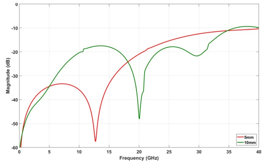
Figure 3 illustrates the insertion loss (IL) of the COM-HPC connectors. Results are shown for both the 5 mm and 10 mm stack heights. PCIe 5.0 supports 32 GTps data rates, which has a Nyquist frequency of 16 GHz. With an IL of less than -1 dB and a flat curve beyond 30 GHz, Figure 3 gives confidence that COM-HPC connectors will perform as advertised.

Figure 4 illustrates the return loss (RL) of the COM-HPC connectors. Results are shown for both the 5 mm and 10 mm stack heights. A good SI rule of thumb is look for where RL = -10 dB. That will give you a good idea of a maximum Nyquist frequency. The figure shows that to be greater than 35 GHz, also providing confidence that COM-HPC connectors will perform as advertised.
COM-HPC Connectors: Ready for Prime Time
So, is 2,088 Gpbs/in2 real? Theoretically, yes, it is.
The combination of the design features of COM-HPC connectors, the recommended differential pair breakouts, and the simulated and tested performance across all signal channels provide confidence to the edge computing industry that COM-HPC connectors increase speed and density.
Matt Burns is Technical Marketing Manager at Samtec. For more than 20 years, he has been a leader in design, technical sales, and marketing in the telecommunications, medical, and electronic components industries. Mr. Burns holds a BSEE from Penn State University.
Samtec
www.samtec.com/COMHPC
Email: [email protected]
LinkedIn: www.linkedin.com/company/samtec-inc
YouTube: www.youtube.com/user/SamtecVideo
@SamtecInc
Facebook: www.facebook.com/samtecinc

Perry Cohen, associate editor for Embedded Computing Design, is responsible for web content editing and creation, podcast production, and social media efforts. Perry has been published on both local and national news platforms including KTAR.com (Phoenix), ArizonaSports.com (Phoenix), AZFamily.com, Cronkite News, and MLB/MiLB among others. Perry received a BA in Journalism from the Walter Cronkite School of Journalism and Mass Communications at Arizona State university.


