
Give Your Industrial Controller the Edge Using Configurable Digital IO
August 17, 2020
Story
Until recently, the standard way of connecting field I/O devices to a programmable logic controller (PLC) has been through traditional wired marshalling.
“57 channels (And Nothin’ on)” sang Bruce Springsteen back in 1992. By comparison with the unquantifiable number of cable (and internet) TV channels available today, back then most people were probably satisfied with 57 channels from which to choose their viewing. Nowadays, 57 channels would scarcely satisfy the requirements of complex automated factory processes and the controllers that manage them (Figure 1).
(Figure 1 Multi-channel PLC)
The labyrinthine nature of modern factories, with ever-increasing numbers of sensors, actuators, motors, solenoids, and valves, has driven the requirement for industrial controllers with ever-more channels to handle huge volumes of data, make decisions, and then output a response. The centralized approached to process control has become a mammoth task, not least due to the rat’s nest of cabling required to make it work. It has become necessary to develop sophisticated new techniques just to try and maintain some physical control of the control systems themselves. However, a change of approach is happening that involves moving process intelligence right to the very edge of the factory floor. In this article we review the challenges and evolution of the centralized process control. We explain the reasons why a change is happening before discussing the merits of an innovative IC that will enable more flexible IO interfaces on the smaller controllers that this emerging paradigm requires.
Wired Marshalling
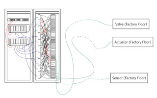
Until recently, the standard way of connecting field I/O devices to a programmable logic controller (PLC) has been through traditional wired marshalling as illustrated in Figure 2. Multi-core cables run wires from the field devices located on the factory floor to the terminal blocks of marshalling panels, usually located in an I/O room. Here, the wiring is cross-marshalled so that each field device is wired to the I/O card, connected the appropriate controller channel.

(Figure 2 Wired Marshalling)
This approach causes many problems. For example, during cross-marshalling, it is difficult to keep track of which wires are coming from and going to, leading to errors if wires are incorrectly connected or even left completely unconnected. Debugging and testing each connection can be time-consuming and laborious for technicians and engineers alike, with the potential to delay the commissioning of a new process. In theory, once debugging is complete, the system should run correctly but additional problems can emerge if unforeseen changes are required late in the project. Sometimes it may be necessary to add a new field device. For example, if a temperature switch is changed to a temperature transmitter, then a digital input will need to be changed to an analog input. An even worse situation occurs if new field devices are added to the system, but the marshalling panel does not have enough spare connections, of the required type, to accommodate them. In this case, the controller would need to be replaced, potentially adding additional cost and delay to the project.
Electronic Marshalling
Electronic marshalling (Figure 3) was developed as an improvement to wired marshalling. It was designed to prevent the human errors associated with the manual element of wired marshalling, namely, the cross-connection of the I/O devices on the marshalling panels. As with wired marshalling, the multi-core cables from the field are routed to the right side of the terminal blocks in the marshalling cabinet by technicians on the factory floor. However, in the I/O room, there is no longer any need to manually connect each terminal block to the appropriate controller I/O channel, as this is handled electronically within the system itself.
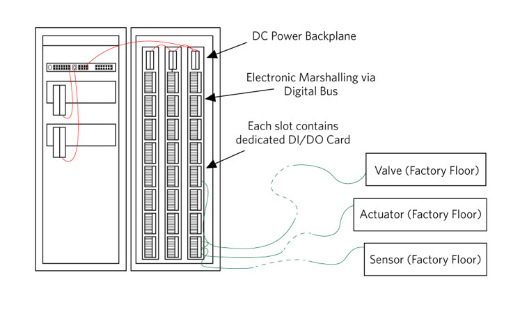
(Figure 3 Electronic Marshalling)
The clear advantage of electronic marshalling is that an I/O device can be connected to a specific controller whenever necessary without physical wiring changes. If at a later stage in the project, changes are made to I/O types, or additional devices are required, then no changes are needed to existing wiring or cabinets. In addition, extra I/O capacity can be added to the marshalling cabinets and then electronically marshalled to the controllers as required. At the heart of the electronic marshalling approach is a rack of portable and replaceable modules or cards. An appropriate card type is inserted into the slot to which the wiring for an I/O field device is connected. For example, a digital input (DI) card would be placed in the slot for a temperature switch. The card would then connect to the appropriate channel of the controller. The function of each controller channel is defined by the type of card (for example, DI or DO) placed in each slot.
While the flexibility offered by electronic marshalling is obvious, there is a not-so-obvious inherent inflexibility. If it is necessary to change the functionality of a controller channel from a DI to a DO, or vice versa, the physical card for the channel must be changed. Also, the total number of DI and DO channels is defined by the number of each type of card in the rack. This places limitations on the flexibility of the electronically marshalled system by constraining the number of DI channels and DO channels in the rack.
Edge Intelligence
Clearly, both of the previous approaches involve wiring multiple input and output devices back to a centralized controller and will ultimately suffer under the burden of sheer scale and the limited numbers of channel types in the IO cabinet. More IO devices mean more and longer lengths of cable to be managed, further increasing complexity. Another problem with this approach is that while sensors provide copious amounts of data that can be uploaded to the cloud for analysis, the inherent latency of a TCP/IP network makes it unsuitable for cloud processing and controlling of industrial processes which need a real-time response to measured data. For this reason, instead of using large centralized controllers, it is becoming necessary to locate multiple smaller real-time controllers right beside the equipment they are controlling at the very edge of the factory floor (“the edge”). These controllers have the computing power and network speed to process and respond instantaneously to the measurements they are making and upload data to the cloud (for example, using 5G or other high-speed protocols). This also allows immediate downloading of new configurations that may become available once measured data has been processed and analyzed by cloud-based algorithms.
Remote I/O
The term for using a controller located at the edge of the factory floor is “Remote I/O.” These controllers must be small, flexible, and robust with sufficient digital IO channels to translate multiple, high input and output voltages (nominally 24V) used by industrial equipment, to the lower voltages (<5V) used by a controller. The IC shown in Figure 4 is ideal for this purpose. It is an IEC 61131-2 compliant, software configurable, 4-channel industrial digital output, digital input device that can be configured on a per-channel basis as either a high-side (HS) switch, push-pull (PP) driver, or a Type 1 and 3, or Type 2 digital input as required. This means that this single IC can be used to provide a controller with 4 digital inputs or 4 digital outputs (or any combination in between) with the flexibility to change channel direction (using only software) if the controlled process requires reconfiguration. Another advantage of this part is that it has an SPI interface that allows several of these ICs to be daisy-chained together to provide controllers with even more digital IO channels. The IC has integrated diagnostics including broken wire detection and CRC error checking of data while a SafeDemagTM feature allows it to safely discharge any amount of inductive load when used as a DO. It is specified for operation with a supply voltage up to 40V (but is tolerant to transients up to 65V) for robust performance. While it is ideal for use in the design of small factory floor-edge (4 channel or more) controllers, it is also suitable for use with existing controllers using the control cabinet arrangement previously described. Using this IC, instead of having to manually swap digital input (DI) and digital output (DO) cards when an industrial process changes, a single card type can be programmed using software to function as either a DI or DO - thereby saving space, simplifying wiring and reducing system downtime.

(Figure 4 Typical application circuit for MAX14906 Quad DI/DO)
Summary
In this design solution, we reviewed the problems associated with the centralized approach to managing factory automation systems. We showed how some of these problems were somewhat mitigated by the development of electronic marshalling. Although a considerable improvement, it is not a panacea to deal with the ever-increasing number of IO devices located on the factory floor. We also explained that while cloud computing is ideal for analyzing the vast amount of data produced by industrial sensors, it is not fast enough to real-time control of industrial processes. For these reasons, smaller, more robust, and adaptable real-time cloud connected controllers (Remote IO) are being moved to the very edge of the factory floor, right next to the processes they control, increasing responsiveness and allowing better web connectivity. Finally, we explained why a robust software-configurable 4-channel Digital IO IC is ideally suited for use in this new generation of industrial controllers and how it can also improve the flexibility of the centralized approach.
Learn More
MAX14906 Quad-Channel Industrial Digital Output/Digital Input
About the Authors
Sean Long is Executive Director, Applications for the Industrial and Healthcare Business Unit at Maxim Integrated. Sean joined Maxim in May 2012. He has a BSc Electrical and Electronic Engineering from Aston University, Birmingham, U.K.
Michael Jackson holds the position of Principal Technical Writer at Maxim Integrated. He has a MEng in Electronic Engineering from Dublin City University.


