
Selecting an Antenna for Your IoT Project
November 13, 2020
Blog

There is a wide variety of embedded antennas for every type of network. This article discusses the options available and some of the factors affecting your choice of antenna.
IoT projects rely on wireless connectivity to link devices, but the best type of connectivity, and therefore antenna technology, depends on the application in question.
Wi-Fi might be a good choice for access points, portable devices, or IP cameras, while industrial applications such as remote monitoring, smart meters, smart buildings, smart cities, manufacturing automation, smart agriculture, and tracking are more likely to use LP-WAN networks such as NB-IoT, LoRa, SigFox, ISM 791-960MHz, or cellular. There is a wide variety of embedded antennas for every type of network.
This article discusses the options available and some of the factors affecting your choice of antenna.
Antenna Selection
Your chosen antenna should fit neatly into the PCB layout and stack-up. Besides this, it must operate to the required range, perform without interference, and use a reasonable level of power. All these performance factors will be verified when the design reaches the testing stage, but an informed choice of antenna and a design that accommodates its requirements will get the design off to a good start.
At first sight, an antenna with a smaller form factor may appear promising, but there is more to consider. The topology of an antenna determines its efficiency, bandwidth, radiation pattern, and gain, so the smallest antenna may not be the best choice.
There are plenty of design factors to consider as well, including the antenna’s proximity to other components, the antenna’s position on the board, the ground plane requirement of the antenna, and the level of interference in the environment where the device is to be used.
Chip, or surface-mount design (SMD) antennas have become extremely popular for small devices. Here we review the main types of SMD embedded antennas.
Surface-Mount Device (SMD) Antennas
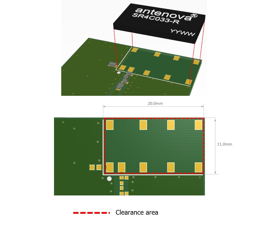
SMD antennas require a ground plane – a space of a certain size that the antenna uses to resonate – below or adjacent to the antenna. This means that the antenna footprint must be free of other components that might interfere with the antenna’s radiation, and there should be similar clearance through all layers on the PCB.
Only the antenna pads and connections to the feed and ground are present in the clearance area (Figure 1). The ground plane requirement for each antenna will be explained in the manufacturer’s datasheet.
Trace Antennas
Trace antennas used to be the obvious choice. They were relatively inexpensive and could be reproduced quickly at scale.
However, they can take up as much as ten times the amount of space on a circuit board as a modern chip antenna. As they are purely two dimensional, they cannot offer the same space-saving features as a planar inverted-F antenna (PIFA), chip, or even patch. In practice, they can be difficult to tune, as small changes to circuit board materials or component layout can affect their performance, and they cannot always be optimized for your device.
Ceramic Patch Antennas
Ceramic Patch Antennas have been popular for positioning applications and can work well in vehicles, but their popularity has declined for a number of reasons.
First, they are highly directional, and must point directly to upwards to the sky to operate effectively. Small ceramic patch antennas can be expensive, but their performance varies due to the shortage of ceramic material available to transmit and receive RF energy.
Smaller patch antennas tend only to support narrow frequency bands, so where a wider frequency is needed, other kinds of antenna are preferable.
PIFA Antennas
PIFAs have become the de-facto wireless solution. They are now ubiquitous in handhelds, wearables, and small IoT devices, primarily because they can deliver high levels of performance combined with a small form factor, but also because they are widely available and inexpensive. They are resonant at one quarter wavelength and yield good SAR properties.
All this makes them a convenient choice for designers. They are easy to integrate, and circuit matching just involves a simple matching circuit. There is one more advantage: They can be placed on top of the PCB ground plane to allow components to be placed underneath the antenna. PIFA is currently the most popular antenna topology thanks to its small form factor and ability to offer high levels of performance.
Electrically Small Antennas
ESAs, or electrically small antennas, are much shorter than their designated wavelength. Whereas some antennas work on ¼ or ½ of a ground plane, ESAs can be as small as 1/10th of a wavelength.
Some of the world’s first antennas used this topology and their performance has recently improved drastically in terms of gain, bandwidth, and field pattern. These antennas can be tiny, maybe smaller than 20 mm. They are relatively immune to proximity and detuning, and can use a technique called beam steering to scale their system capacity relatively easily.
Magnetic Loop Antennas
Finally, there are magnetic loop antennas, which couple to the magnetic field wave in the region near the antenna. They work perfectly in ultra-small devices that require high levels of performance within a compact form factor. They are resistant to de-tuning and are a good choice for wearable and handheld devices where PCB space is at a premium and performance is critical.
Other Antenna Types and Topologies
SMD is not the only solution for embedded wireless; there are other antenna topologies which may be useful for certain IoT and embedded designs.
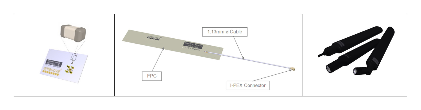
There are flexible and external antennas, which both offer advantages. The flexible antenna does not sit directly on the PCB and does not require a ground plane. External antennas are situated to the exterior of the device, work well with various ground plane sizes, and effectively operate in free space, which simplifies antenna integration.
Flexible Antennas
If there is not much space within the device, a flexible antenna (FPC) may be a good choice. The FPC need not be placed on the actual PCB – it is connected to the system by its own integrated I-PEX cable.
The FPC does not require a ground plane to radiate, so it may be tucked inside the housing of the device. This can help save space on the PCB, but the integration of an FPC antenna needs care as the cable actually becomes part of the antenna when it radiates.

Terminal Antennas
Where an application requires mission-critical wireless performance, terminal antennas may offer opportunities to obtain the highest levels of performance – particularly in environments where there is other RF noise. These antennas are much larger and are placed to the exterior of a device.
They can achieve outstanding performance in free space without any in-device tuning or matching.
Board Size and Layout: Saving Space
The size and layout of your PCB design will probably dictate your choice of antenna. Space is always at a premium, so a compact, low-profile antenna is usually a good choice.
Remember that the antenna should be placed away from other “noisy” components such as batteries, motors, and metal parts of the design, which could cause interference and affect the wireless performance of the device. The outer casing for the device may cause issues if it is manufactured from metal, so plastic is often a safer choice
The ground plane requirement will be a factor in determining the layout of the board. If space is tight, a chip antenna designed to operate on one of the edges or a corner of the PCB may be a good option and save a useful amount of space on the board.

If the antenna is designed for a corner, it may be available in left and right options to offer the designer more choice of position on the PCB.
The manufacturer’s datasheet will explain exactly how the antenna should be situated and integrated into the design.
The IoT Environment
Finally, a good wireless design should be created to operate in the environment where it will be used.
IoT solutions are often found in commercial and industrial settings. There are IoT applications in factory automation, vehicle and container tracking, and metering solutions for smart buildings. However, these may not be good environments for RF. When there are metal objects close by, or motors, or other wireless devices, or even people, the wireless performance may be affected.
Testing the design in an anechoic chamber will show how the device will perform in a perfect environment, but every prototype should also be tested in its real-world working environment. Testing is the first step to achieving a working design and gaining regulatory approval.
Geoff Schulteis is Senior Antenna Applications Specialist with Antenova Ltd. Please see www.antenova.com for more information about embedded antennas and their integration.


