
Using ADASIS Version 3 for Precision Localization in Highly Automated Driving, Part 2
January 29, 2019
Story

The EB positioning solution uses the LbL data within its EB robinos Positioning product. The results are an improved global position and a local position represented as accumulated delta movements.
A major prerequisite for highly automated driving systems using high-definition map data is the knowledge about the vehicle's position. This position needs to have a much higher precision than can be achieved with a GNSS sensor alone. Therefore, various other sensor systems like gyroscopes or odometers can be used to enhance the position estimation. This contribution describes a system using another input, ADASISv3 map data, to improve the positioning. The map data is received from a map database and then compared to traffic sign measurements from a camera system.
Usage of Localization Data for Positioning
The EB positioning solution uses the LbL data within its EB robinos Positioning product. This positioning product takes all available positioning information, like e.g. GPS and wheel ticks, and tries to combine them to the best possible position. Furthermore, it tries to reduce the individual noise of each sensor through corresponding mathematical modeling. The results are an improved global position and a local position represented as accumulated delta movements from the beginning of the drive.
The LbL measurements are integrated in this overall positioning system as correction values to the continuous positioning, because of the low-frequency character of this measurements. Each time a LbL localization, including confidence estimation represented as variance, is transferred to the overall positioning, the error to the continuous localization is calculated and corrected by updating the overall localization.
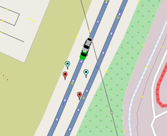
Figure 5 gives a small overview of the different values within the overall positioning system. The blue markers represent the landmark position, provided by the ADASISv3 data and the red markers show, where the LbL system measured these landmarks relative to the vehicle position. The offset between these markers shows that an accumulated positioning error already is present in the localization system. The system itself estimates that it is located at the position of the gray car, but the green car shows the position where the localization takes place after the correction from the LbL measurement is added to the overall localization.
Experimental Results
To verify the system capabilities, the LbL system was installed in one of EB's test vehicles. It was tested on the highway A391 near Braunschweig, Germany. During these test drives, the position from a high precision GPS system and the position from the LbL system were recorded.
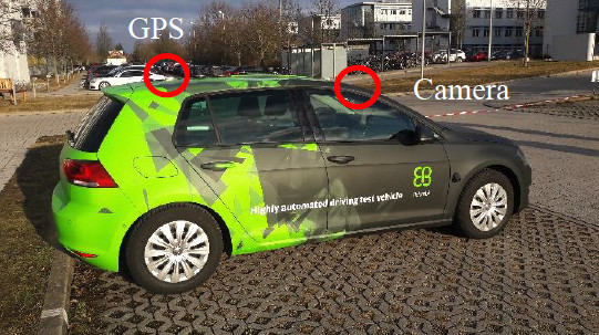
Figure 6 shows the test vehicle, a 2014 VW Golf 7, which is equipped with a differential GPS inertial measurement unit from OxTS, an RT3003, as a reference sensor. The installed camera system is a Mobile Eye model 630. It delivers the traffic signs measurements via a CAN bus. Moreover, the positioning system uses vehicle sensors for wheel ticks and gyros available on the main CAN bus of the vehicle. As the authors did not manage to get traffic sign information directly from the databases of the major map providers (data will be available later in 2019), the reference data were measured from aerial imagery.
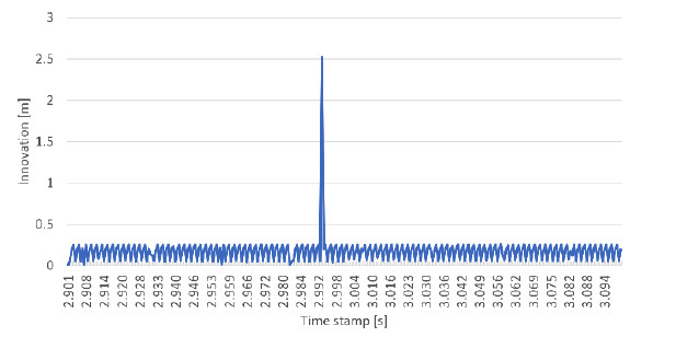
As shown in Figure 7, the usual innovation between two measurements of the positionings output system is far below 0.5m. However, at about 2.9 seconds, the innovation raised to about 2.5m. At this point of time the measurements from the traffic sign camera are considered to correct the vehicle's position. As described in the scenario in Section 5, the vehicle detects two traffic signs and matches them to two traffic signs in the map database while the vehicle is moving at about 80 km/h. The two traffic signs are detected at different longitudinal positions even when the signs are aligned as shown in Figure 5. At the time of this paper's composure, it could not be determined whether the camera actually detects the signs at different locations or whether a latency on the bus caused the difference in position.
In Figure 8, the impact of a LbL measurement to an individual position variable is plotted. The blue line represents the position of the positioning system based purely on interoceptive sensors. The influence of GPS noise can be seen in the jitter of this line. The LbL system is represented in orange. As soon as the LbL measures a position at about 6s, its influence on the overall position is visible, as the correction in the blue line can be observed.
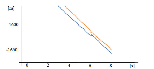
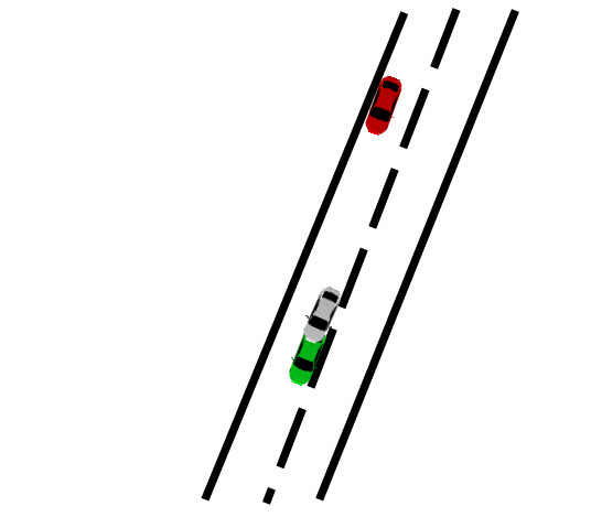
Figure 9 visualizes this overall positioning correction. The green car represents the position where the positioning would have localized itself without a LbL correction. The red car shows the place where the LbL localization took place. The grey car indicates the position where the car localizes itself with the LbL-based position correction applied.
Conclusion
An exteroceptive localization system based on geo-referenced landmarks can reduce the absolute error where these landmarks are available. With this contribution, the authors showed a proof of concept of how this type of system can be implemented using data delivered via ADASISv3. Additionally, it described how at this point in time the system could make use of HD map databases directly. It is most likely that the reference data for traffic signs will be available soon and the manually acquired traffic sign locations can be replaced.
The contribution gives an overview of the processing chain of the LbL system. The system is then used with real-world data and the effects of the measured data could be shown.
Using landmarks for localization can improve a position software component in situations where GPS is not available and interoceptive sensors will generate a drift.
The development of this proof of concept will be continued in the EB robinos Positioning product. At the moment, EB offers a fully featured positioning software component for automotive grade localization based on wheel ticks, accelerometers, and other interoceptive sensors as well as GPS for global positioning. The next generation of this product will also include landmark-based localization as well as SLAM-based point clouds (e.g. from LIDAR or camera).
Bibliography
[1] R. R. Boyd, "A Discourse on Winning and Losing," 1976.
[2] S. A. E. International, "J3016 - Taxonomy and Definitions for Terms Related to Driving Automation Systems for On-Road Motor Vehicles," 2018.
[3] I. N. Bronstein, K. A. Semedjajew, G. Musiol and H. Mu?hlig, Taschenbuch der Mathematik, 5 ed., Thun und Frankfurt am Main: Verlag Harri Deutsch, 2001.
[4] A. D. A. S. I. S. Forum, "ADASIS v3 Protocol - Specification v3.1.0 - Release Candidate 1," 2018.


