
Simplify GNSS Receiver Design
April 12, 2019
Story

Global Navigation Satellite System (GNSS) receivers process satellite signals to compute position, velocity, and time.
Introduction
Global Navigation Satellite System (GNSS) receivers process satellite signals to compute position, velocity, and time. These receivers provide a wide range of navigation solutions from marine and avionics to in-vehicle and still camera systems (Figure 1).

Even though a wide range of applications can use the generic GNSS receiver information, these systems all rely on the capability of the receiver's front-end solution. The receiver’s front-end must receive and properly condition the satellite’s weak analog signal towards a useful digital output.
This article discusses the requirements and challenges of a typical receiver front-end and presents an integrated solution that receives signals from not one but four satellite navigation systems, thereby simplifying the design from multiple receiver devices to one.
Global Navigation Satellite Systems – GNSS
Several constellations of orbiting satellites exist to provide autonomous geo-spatial positioning. Any navigation solution provided by a GNSS receiver is based on the computation of its distance to four or more satellites and the decoding of the incoming signals. A GNSS receiver extracts the individual satellite signals and uses them to calculate position, velocity, and time at the receiver’s location.
Front-End Considerations
The main functions of an RF front-end IC are to amplify, down-convert, filter, and sample the GNSS signal while adding as little noise as possible (Figure 2).
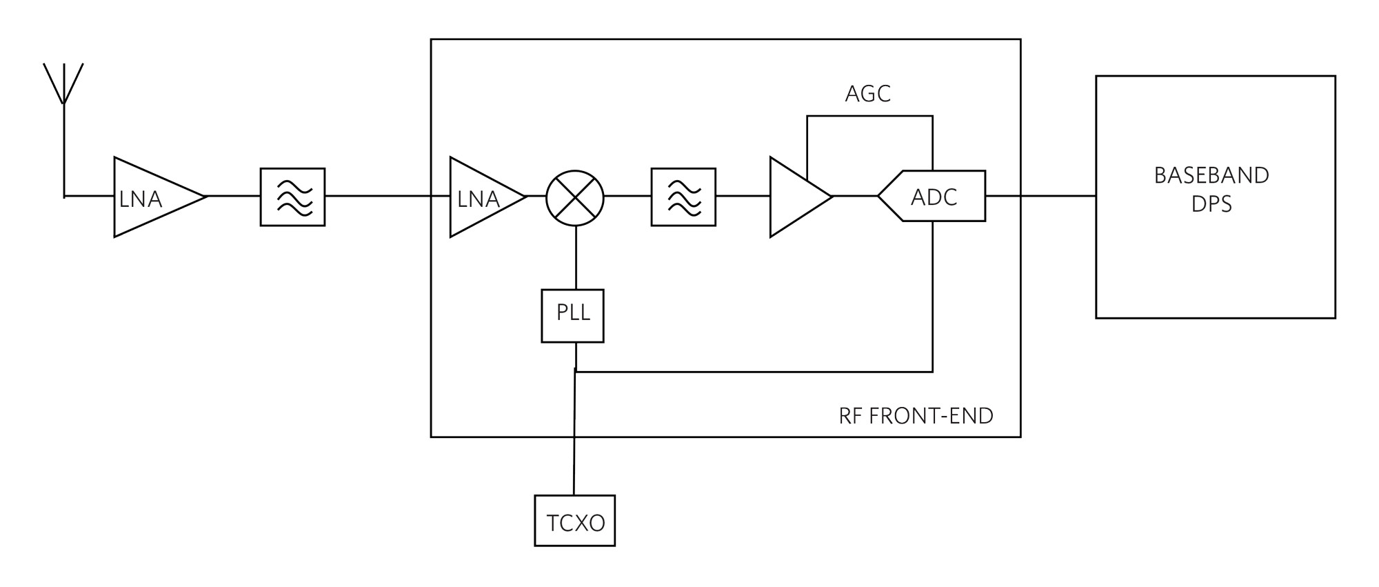
The key areas of concern with the front-end circuitry of the GNSS receiver include low-noise/high-gain/IF (intermediate frequencies) modulation, filtering, and analog-to-digital conversion.
At the front end of the GNSS receiver there is an active or passive antenna to capture and potentially amplify very weak satellite signals. There may also be a SAW filter to reduce interfering signals. The first stage of signal processing in the RF front-end IC is low-noise amplification through a low-noise amplifier (LNA).
Low Noise: The low GNSS signal strength needs a highly sensitive LNA stage. In this stage, a low-noise figure (NF) is the most important specification to provide high sensitivity to the GNSS signal.
High Gain: The received GNSS signal is typically approximately -130dBm at the antenna. In preparation for the analog-to-digital conversion, the total amplification on the signal needs to be approximately 115dB. In this system, gain is provided through the LNA, the IF filter, and a programmable gain amplifier (PGA). The gain of the PGA may be controlled via an automatic gain control (AGC) loop that maintains an optimal signal level at the ADC input.
Intermediate Frequency (IF): The front-end receiver must down-convert to an IF by 10MHz or possibly DC. The mixer stage accomplishes this down-conversion and creates the in-phase (I) and quadrature (Q) signal components.
Filtering: The main purpose of filtering after the mixing stage is to reduce the noise bandwidth and attenuate interfering signals prior to the main amplification stage.
There may be interfering signals around the GNSS receiver system. These interferers can be unintentional, such as a GSM-1800 cellular wireless signal, or they can be hostile interfering signals. Hostile interfering signals are often called jammers. A common interferer rejection technique is to use a SAW filter. Although, if a jammer is right on top of the GNSS signal, this will not help.
ADC: Typically, the front-end uses 1-, 2- or 3-bit ADCs to produce the digital I and Q output signals. There are diminishing returns on the signal-to-noise-ratio (SNR) if the number of ADC bits is increased beyond three. However, sometimes higher resolution ADCs are used to provide anti-jamming capability.
Driving Towards the Simple Solution
The integrated front-end receiver solution must have the critical operation and specifications while being able to receive signals from the major GNSS constellations. The MAX2769C significantly reduces the development time for GNSS receivers by integrating the necessary RF front-end functions into one chip.
There are two LNAs. One LNA features a 0.9dB noise figure and 19dB of gain, for use with passive antennas. The other LNA has a 1.5dB noise figure with slightly lower gain. The second LNA is appropriate for active antenna use (Figure 3). The cascaded noise figure of the entire receiver, when using the high-gain LNA, is typically 1.4dB.

The MAX2769C can detect the presence of an active antenna and automatically selects the lower gain LNA.
A fractional-N PLL provides flexibility in XTAL frequency and IF. The IF filter can be configured as a complex polyphase filter for non-zero IF or as a lowpass filter for zero IF. The filter bandwidth can be selected for the bandwidth of the signal to be received.
The on-chip ADCs can be bypassed if the use of an external higher resolution ADC is preferred.
The MAX2769C can receive L1 band signals from the GPS, GLONASS, Galileo, and BeiDou satellite systems.
Conclusion
The MAX2769C’s IF filter adjustable frequency allows the designer to access not just one, but all four constellations in the sky. The MAX2769C GNSS receiver has the flexibility of receiving signals from GPS, GLONASS, Galileo, and BeiDou satellite systems, while providing a high level of integrated performance. This device replaces several individual receivers on a PCB with a simple compact solution.
Glossary Terms
LNA: Low Noise Amplifier
IF: Intermediate Frequency
ADC: Analog-to-Digital Converter
GNSS: Global Navigation Satellite Systems
GPS: Global Positioning System is the United States GNSS
GLONASS: Russian Ministry of Defense GNSS.
Galileo: Galileo is a GNSS that is currently being developed by the European Union (EU) through the European Space Agency (ESA).
BeiDou: Chinese GNSS
Learn More:
MAX2769C Universal GNSS Receiver
Design Solution No. 75
Rev 0; February 2018
Bonnie Baker is an electronical engineer who has written three analog design books, starting with A Baker’s Dozen: Real Analog Solutions for Digital Engineering (2005). In past roles, Burr-Brown, Microchip, Texas Instruments, and Maxim Integrated facilitated her involvement in analog design and analog systems for the last 30+ years. Bonnie holds a Masters of Science in Electrical Engineering from the University of Arizona (Tucson, AZ) and a bachelor’s degree in music education from Northern Arizona University (Flagstaff, AZ). In addition to her analog design fascination, Bonnie has a drive to share her knowledge and experience through the authorship of over 500 articles, design notes, and application notes.


