
Measuring and Reducing Power Consumption Using Early System-Level Power Modeling
April 22, 2019
Blog

Power management is a critical design factor in electronics. Product features of consumer application, space-based systems, data center solutions, high-performance computing are constrained by budget.
Power evaluation in the early stages of the product design has been performed mostly using analytical methods such as spreadsheets. These spreadsheets typically contain the power for different tasks or devices and the sheet added the worst case or the average of the power. These methods provide some insight but they fail to capture the concurrent nature of the power consumption. Moreover these models are evaluated in isolation and do not incorporate the task timing and cover the entire design space of use cases.
Power management is a critical design factor in electronics. Product features of consumer application, space-based systems, data center solutions and high-performance computing are constrained by the power budget. Reasons are customer demand, weight of the Lithium-Ion batteries and physical space to install the solar panels. The efficiency of the application task graph on the target hardware resource determines the energy consumption and dictates the battery selection, energy harvesting and additional power management.
Power must be looked at from a holistic view of power consumption of electronics, displays, electric and MEMS technologies, battery and other energy storage, and harvesters such as motors and solar panels. At the system-level, the energy usage is determined by user-cases, number of starts and duration of each run, power states of complex electronics, state-machine to change state based on activity or inactivity and power minimization algorithm. In the battery it is about the lifecycle that is impacted by request spikes, charging rates, thermal and physical shocks and attributes of each battery family. The energy harvester is about the correct angle or coils, availability of the source such as sun rays and nuclear material, and spikes in the requirement.
Over the years, a number of power management algorithms have been proposed. Over time, these algorithms have become ingrained and their limitations exposed. As a result, these algorithms have been evolved with constraints or replaced with software-based power management. The smaller semiconductor process size has increased the leakage power, larger processors has increased thermal insulation requirements, and the increased number of high bandwidth sensors has created the need for a higher drag during shorter durations. Power can also be impacted by the reduction in data movement, distribution of software tasks, task scheduling and selection of alternate topology.
Experiments
Let us take a couple of simple examples and look at the impact on power by various architecture decisions. One is that of a hybrid vehicle, the other is a Cubesat and the third is a multi-core System-on-Chip or Processor.
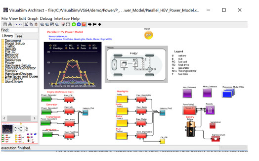
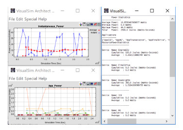
In the Hybrid vehicles, we look at the energy generated by the motor that charges the battery and provides power to all nodes in the system. The block diagram of the system simulation in VisualSim is shown in Figure 1. For the particular configuration, the generated reports are captured in Figure 2. As you can see from the total power plot, the peak power is requested for a very small duration of time. You can also see which devices are activated concurrently and which devices are rarely or randomly turned on. This power profile provides visibility into periods of low power activity, opportunities to disable devices or networks, and size the battery.
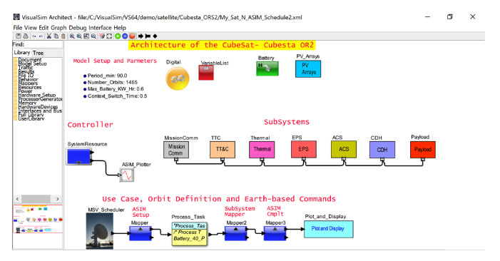
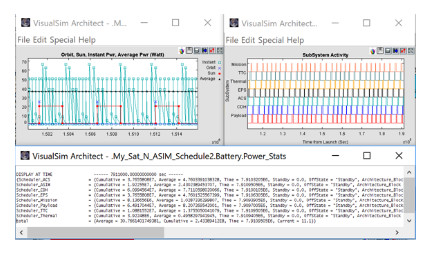
The second design is of a CubeSat system that is made up of multiple sub-systems and receives power from a Photo-Voltaic Cell. The design incorporates the behavior of the satellite during direct sun view and during an eclipse. The use-cases are defined on a per-orbit and the processing takes into consideration the time of day, number of tasks enabled, sub-system active during each task and duration of the activity. The processing devices are set to lower speeds during discharge and are at full performance during charging periods. Figure 3 shows the block diagram of the CubeSat that contains four parts: Task Graph of the use cases per orbit, Battery and photo voltaic cells, sub-systems and their connectivity to the Bus and the Scheduler. Figure 4 shows the average and instant power across 10,000 orbits, activity of the sub-systems based on the number of active tasks, and the power details for each sub-system.
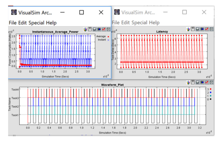
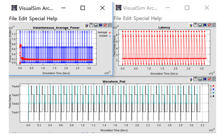
The last example is of a multi-core System-on-Chip with a custom dispatcher as opposed to a Real-Time Operating System. There are four threads running concurrently with different processing times. In this example, we evaluate the impact of scheduling tasks as they arrive versus providing offsets. The evaluation metrics is the increased latency versus lower power consumption. Figure 5 shows the simulation results of the multi-core architecture for the power and latency with no offset of the tasks. As you can see, all four cores are in use. Figure 6 shows the similar plots with an offset of 35.0 use between the concurrent tasks. You can see how the latency is not impacted at all but the number of active cores has reduced to two. We reduce cost and also power consumption. If the requirements can handle the extra delay, a much better solution is available.
For the analysis we used VisualSim from Mirabilis Design. VisualSim Architect is a graphical modeling and simulation for the architecture exploration of electronics and semiconductors. We used the pre-built libraries and standard reports from VisualSim for our design analysis. The modeling environment allowed us to capture the timing and power consumption of the electronics, electric sub-systems and MEMS. As a result, we could get a global view of the full system. The multi-core architecture used a quad-core cycle-accurate model of an ARM Cortex A53. We selected the A53 because of the wide-spread availability of System-on-chips (SoC) from processor vendors and the FPGA vendors have incorporated it into their new generation of MPSoC FPGAs. All three models were constructed and evaluated in about two weeks time.
Conclusion
System-level modeling can be used to measure the power consumption at the beginning of the project. Models must incorporate the timing, power and functionality of all the sub-systems into the architecture model. This ensures that you can view the interaction between the different parts of the system and also see how you gain advantages by sharing resources, while not forgoing any performance. To evaluate the real-benefit of system modeling, we ran the tests across large systems, embedded architectures and semiconductors. We found that the same methodology can be applied to these segments even though the evaluation may be different. VisualSim Architect had the libraries for all these application segments and this allowed us to speed up the model development.


