
An Almost Pure DDS Sine Wave Tone Generator: Part 3
March 24, 2020
Blog

In this final part of the series, we will cover how to select the reconstruction DAC and complete the DDFS system.
In part 1 of this series, we discuss how it is possible to design a very accurate sine wave generator based on the direct digital frequency synthesis (DDFS) principle, but implemented in software onto a floating-point DSP processor. In part 2, we covered how to implement a high precision NCO in software. In this final part of the series, we will cover how to select the reconstruction DAC and complete the DDFS system.
The first temptation would be to select a high precision DAC with the best specification in terms of nonlinearity error (INL and DNL), like the AD5791, a 20-bit accurate DAC. But its resolution is only 20 bits and its R-2R architecture does not favor the reconstruction of signals, and especially the production of very pure sinusoids, because of its large glitches during input code transitions. Conventional DAC architectures built around binary weighted current generators or resistor networks are sensitive to digital feedthrough and digital switching impairment such as external or internal timing skew and other switching asymmetries of the digital input bits, particularly during major transitions for which the energy variation is consequent. This induces code-dependent transients, resulting in harmonic spurs of high amplitude.
At 20+-bit resolution, the use of an external ultralinear and fast sample and hold amplifier to deglitch the output of a DAC does not help much as it generates its own transients in tens of LSBs and introduces group-delay nonlinearity due to the resampling. For signal reconstruction, primarily in communication applications, the glitch issue is solved with the use of segmented architectures mixing fully decoded sections for the MSBs and binary weighted elements for the lowest significant bits. Unfortunately, no such commercial DAC currently exists beyond 16-bit precision. Instead of the fully predictable behavior of the NCO, the DAC errors are difficult to estimate and simulate accurately, especially when the manufacturers’ dynamic specifications are rather weak or nonexistent, except for the DACs or ADCs dedicated to audio applications. The interpolating oversampled and multibit sigma-delta DAC then seems the only solution to be good enough for the job. With a resolution up to 32 bits, ultralow distortion, and high SNR, these state-of-the art converters are the best candidates for signal reconstruction over low to medium bandwidths. Trying to get the best noise and distortion performance within the audio spectrum or a slightly wider band (20 kHz or 40 kHz bandwidth), the best sigma-delta DAC within the Analog Devices portfolio is the AD1955 audio stereo DAC, still one of the best audio DACs available on the market, despite its resolution being limited to 24 bits.
Introduced in 2004, this audio DAC is based on a multibit sigma-delta modulator and oversampling techniques aided with various tricks to mitigate distortion and other plagues inherent to this principle of conversion.8
The AD1955 has got one of the best interpolation LP FIR filters of its kind, even today. It has a very high stop-band attenuation (≈–120 dB) and a very low in-band ripple (≈±0.0001 dB). Its two (left and right channels) DACs can operate up to 200 kSPS, but the best ac performance is achieved at 48 kSPS and 96 kSPS with a typical EIAJ standard, A-weighted, 120 dB figure for both its dynamic range and SNR in stereo mode. In mono mode, for which the two channels are simultaneously combined out of phase, a performance improvement of 3 dB can be expected. However, for wideband applications, these specifications are somewhat unrealistic since they are synthetic and restricted to the 20 Hz to 20 kHz bandwidth. Out-of-band noise and spurs are not considered beyond 20 kHz, partly because of the EIAJ standard, A-weighted filter, and audio industry specification definitions. This band-pass filter specific to audio measurements mimics the human ear frequency response and yields 3 dB better results over unfiltered measurements.
DDFS Hardware Demonstration Platform: Sine Wave Reconstruction with the AD1955
The complete DDFS has been implemented using two evaluation boards, one supporting the DSP processor and one for the analog signal reconstruction with the AD1955 DAC. The second-generation SHARC ADSP-21161N evaluation board was chosen for availability reasons as well as its ease of use and lean configuration for any audio applications. Still in production, the ADSP-21161N was designed a while ago, to support industrial, high-end consumer and professional audio applications, providing up to 110 Mips and 660 MFlops or 220 MMACS/s capabilities. Compared to the most recent generations of SHARC processors, the ADSP-21161N differs mostly by its short, 3-stage instruction pipeline, an on-chip, 1 Mb, only triple port RAM, and a reduced set of peripherals. The final and most critical stage of the precision tone generator is based upon the AD1955 evaluation board, which must faithfully reconstruct the analog signals from the samples delivered by the software NCO. This evaluation board carries an antialiasing filter (AAF) optimized for the audio bandwidth to meet the Nyquist criterion and has a couple of serial audio interfaces to support PCM/I2S and DSD digital streams besides the usual S/PDIF or AES-EBU receiver. The PCM/I2S serial link connector is used to connect the AD1955 DAC board to serial ports 1 and 3 connector (J) of the ADSP-21161N EVB. Both boards can be configured for I2S PCM or DSP modes of operation at 48 kSPS, 96 kSPS, or 192 kSPS sampling rates. The DSP serial port 1 generates the left and right channel data, the word select or L/R frame sync and the SCK bit clock signals needed by the digital input interface of the dual-channel DAC. The serial port 3 is just used to generate the DAC master clock, MCLK, required for the operation of the DAC interpolation filters and the sigma-delta modulators running 256 times (by default) faster than the input sampling frequency (48 kSPS). As all the DAC clocking signals are generated by the DSP, the board original, low cost Epson clock oscillator has been changed for an ultralow noise oscillator CCHD-957 from Crystek. Its phase noise specification could be as low as –148 dB/Hz at 1 kHz for a 24.576 MHz output frequency.
On the analog output side, active I/V converters must be used to hold the AD1955 current differential outputs at a constant common-mode voltage, typically 2.8 V, to minimize the distortion. Ultralow distortion and ultralow noise high precision operational amplifiers like the AD797 are used for this purpose and to handle analog signal reconstruction as well. As the two differential outputs are processed separately by the DSP, the stereo output configuration with its AAF topology has been selected instead of the mono mode. This AAF was simulated with LTspice XVII with results given in Figure 6. As the last section of the filter is passive, an active differential buffer stage should be added like the recently introduced ADA4945. This low noise, ultralow distortion, fast settling time, fully differential amplifier is the almost perfect DAC companion to drive any high resolution SAR and sigma-delta ADCs. With a relatively large common-mode output voltage range and superb dc characteristics, the ADA4945 provides exceptional output balance and contributes to the suppression of even-order harmonic distortion products.
The EVB third-order filter has a –3 dB cutoff frequency of 76 kHz with an attenuation of only –31 db at 500 kHz. The in-band flatness is very good, but the out-of-band attenuation of this LP filter must be seriously improved, even if restricted to a pure reconstruction audio application. This is mandatory to reject the DAC shaped noise as well as the modulator clock frequency MCLK. Depending upon the use of the software DDS either for a single tone generator or an arbitrary waveform generator (AWG for complex waveforms), the AAF will be optimized for out-of-band attenuation or group delay distortion. As a practical example and comparison, the old but renowned SRS DS360 ultralow distortion function generator has been designed with a seventh-order Cauer AAF for a similar sampling rate. The signal reconstruction lies on the AD1862, a serial input 20-bit segmented R-2R DAC aimed at digital audio applications. The AD1862 was able to sustain 20-bit word sampling rates up to 768 kHz (×16 fS) and exhibits exceptional noise and linearity specifications. Its single-ended current output leaves the choice to use the best amplifier for the external I-to-V conversion stage.
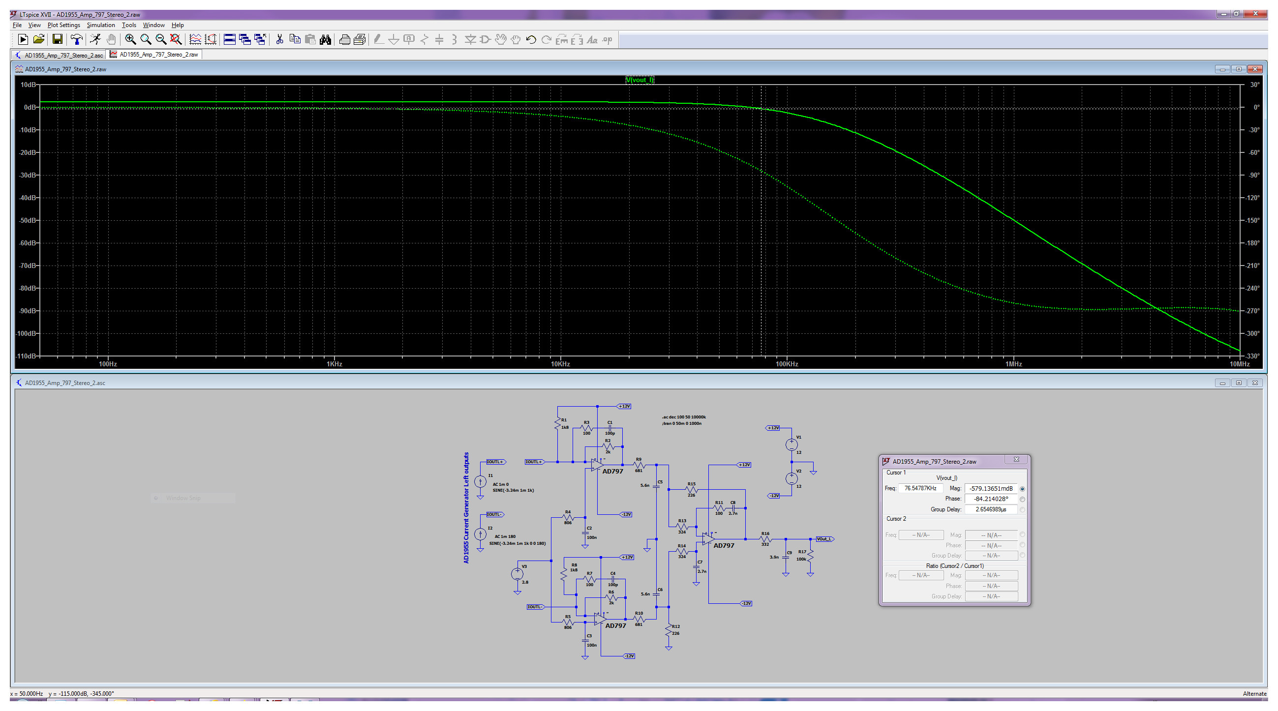
Figure 6. The LTspice simulated frequency response of the AD1955 EVB third-order antialiasing filter (stereo configuration).
The AD1955 and SHARC DSP combination was tested against several high resolution SAR ADCs such as the AD4020 with no external selective passive filters in between. By default, the basic AD4020 evaluation board offers no other choice than the on-board ADA4807 drivers. The simple circuitry to bias the ADC inputs at the V_REF/2 common-mode voltage imposes a rather low input impedance of 300 Ω and requires either signal isolation, ac coupling, or the use of an external differential amplifier module such as the EVAL-ADA4945-1. The AD4020 reference design board described in the circuit note CN-0513 is a better choice. It includes a discrete programmable gain instrumentation amplifier (PGIA), which provides a high input impedance and accepts ±5 V differential input signals (G = 1). Although these AD4020 boards and their SDP-H1 controller lack the capability to support coherent sampling acquisition, they allow decent waveform capture lengths for samples, ranging up to 1M. Thus, long FFTs with selective windowing are possible, providing both fine frequency resolution and a low noise floor. For example, with the seven-term Blackman-Harris window, the 1 Mpts FFT plot shown in Figure 7 illustrates the level of distortion of the AD1955 for a 990.059 Hz generated sine wave. The second harmonic is the largest distortion component and the largest spur at –111.8 dBc over a 350 kHz bandwidth. However, when considering the whole ADC Nyquist bandwidth of 806 kHz, the SFDR is limited by the DAC sigma-delta modulator and interpolating filter frequency and its second harmonic (384 kHz and 768 kHz).
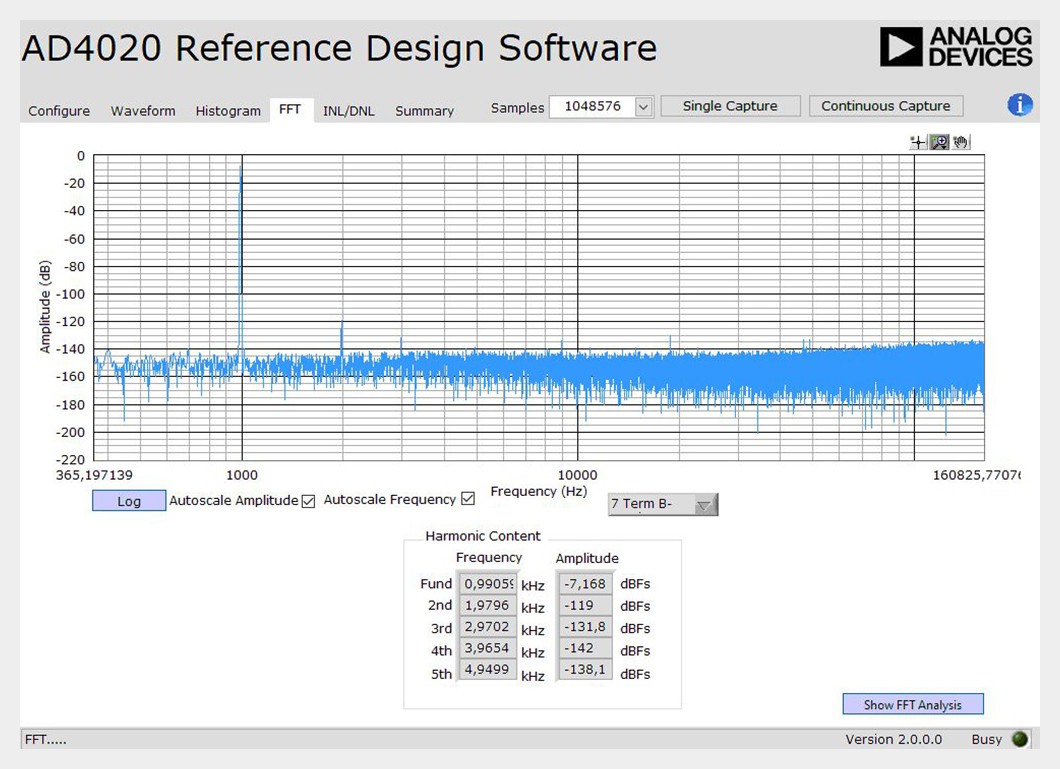
Figure 7. 1 M points FFT analysis shows pretty good distortion with H2 lower than –111 dBc, with the largest spur in the 10 kHz to 200 kHz band for a 1 kHz input frequency. The noise floor sits at about –146 dBFS.
In the same conditions, test trials were conducted on the vintage AD1862, which exhibited a slightly different spectral behavior. Placed in differential configuration, the two 20-bit DACs clocked at about 500 kSPS reported a noise floor of –151 dBFS, a THD of –104.5 dB for a sine output level of 12 V p-p at 1.130566 kHz. The SFDR over the AD4020 Nyquist bandwidth (806 kHz) is close to 106 dB limited by the third-harmonic. The DAC reconstruction filter based around two AD743 low noise FET amplifiers is a third-order similar to the one of the AD1955 evaluation board, but with a cutoff frequency of 35 kHz at –3 dB.
To become effective, the DDS-based generator requires a decent filter capable of an attenuation greater than 100 dB at about 250 kHz for a generated dc to 25 kHz CW signal frequency range. This can be achieved with a sixth-order Chebyshev and even a sixth-order Butterworth LP filter for a perfect in-band flatness. The order of the filter will be minimized to limit the number of analog stages and their nonidealities such as noise and distortion.
Conclusion
Preliminary and out of the box tests performed on standard evaluation boards demonstrate that the processor-based DDS techniques for conventional sine wave CW generation with top performance are within reach. The –120 dBc harmonic distortion figure could be met with a careful design of the reconstruction filter and the analog output buffer stage. The DSP-based NCO/DDS is not only restricted to the generation of single tone sine waves. By using an optimized AAF (Bessel or Butterworth) with an appropriate cutoff frequency and no other hardware change, the same DSP and DAC combination can be disguised into a high performance AWG to produce any type of waveform, for example, to synthesize fully parametrizable multitone sine waves with a full control of the phase and amplitude of each component for IMD testing.
Since floating-point arithmetic is crucial for applications requiring high accuracy and/or high dynamic range, today the SHARC+ DSP processors such as the low cost ADSP-21571 or the SoC ADSP-SC571 (ARM and SHARC) are the de facto standard for real-time processing up to an aggregated sampling rate of 10 MSPS. Clocked at 500 MHz, the dual SHARC cores and their hardware accelerators can provide more than 5 Gflops computation performance and offer tons of internal specialized SRAM, the basic ingredients demanded by the tasks for the generation of any kind of waveforms, as well as for complex analysis processing. This type of application shows that the systematic use of hardware programmable solutions is not mandatory for handling precision digital signal processing. Floating-point processors and their complete development environments allow easy and fast code portability from simulators such as MATLAB, as well as rapid debugging thanks to Analog Devices’ CCES and VDSP++ C and C++ compilers and their full suite of simulators and real-time debuggers.
About the Author
Patrick Butler is a field applications engineer with Analog Devices’ south Europe sales organization, supporting the French global market and some ADEF customers. He has been with ADI since 1984, supporting the DSP building blocks ICs, as well as high speed converters. Previously, he worked as a design engineer in the ATE division of Schlumberger in Saint-Étienne, France for five years, and then occupied several application engineer and FAE positions at Matra-MHS in Nantes, AMD and Harris SC-Intersil. Today, his main hobby is collecting vintage sound components to build active, high efficiency horn loudspeaker-based systems with the help of his two sons.
8 Robert Adams, Khiem Nguyen, and Karl Sweetland. “A 113 dB SNR Oversampling DAC with Segmented Noise-Shaped Scrambling.” IEEE, February 1998.
References
ADSP-21000 Family Application Handbook Volume 1. Analog Devices, Inc., May 1994.
A Technical Tutorial on Digital Signal Synthesis. Analog Devices, Inc., March 2001.
Butler, Oscar. “Internship Report Summer 2017: High Precision Oversampled 20-Bit Ultra Low Power Acquisition System.” Analog Devices, Inc., 2017.
Crawford, James A. Advanced Phase-Lock Applications: Frequency Synthesis. AMI, LLC, May 2011.
Evaluation Board User Guide UG-048. Analog Devices, Inc., February 2010. EV-4020-REF-DGNZ Reference Design Board User Guide UG-1280.
Analog Devices, Inc., May 2019.
Goldberg, Bar-Giora. Digital Techniques in Frequency Synthesis. McGraw-Hill, August 1995.
Model DS360 Ultra Low Distortion Function Generator. Stanford Research Systems, 1999.
Symons, Pete. Digital Waveform Generation. Cambridge University Press, November 2013.
AD1862 data sheet. Analog Devices, Inc., July 2011.
1241-2010 - IEEE Standard for Terminology and Test Methods for Analog-to-Digital Converters. IEEE, January 2011.


