
Testing for EMI/EMC Compliance with RF Modules
July 17, 2019
Blog

This pushes developers into the murky area of RF design and test, not just for connectivity, signal integrity, and interface interoperability, but also added complexity.
Thanks to the Internet of Things (IoT), what were once standalone embedded systems are now being connected using one or more of a wide number of RF interfaces. This pushes developers into the murky area of RF design and test, not just for connectivity, signal integrity, and interface interoperability, but also added complexity thanks to RF emissions and EMI/EMC compliance to FCC, CE, and CISPR regulations.
To get their design connected, developers typically take one of two routes: roll their own design from the ground up using an IC from Nordic Semiconductor, Silicon Labs, Texas Instruments, and a host of others. This is usually a good idea if large volumes are expected, as it saves money and space over the long run, assuming the design is done well. However, RF design, layout, and shielding are difficult, even the antenna choice and placement can be a problem. Then there’s testing to FCC, CE, and CISPR regulations to ensure it passes. All this adds extra steps that can nullify both budgets and project deadlines.
To circumvent much of this, developers can choose a full RF module. This has the attraction of being quicker and more reliable. It also doesn’t require having a full RF design team on hand, which few embedded systems startups, or even larger companies, can boast about having. RF designers demand a premium, and rightly so. They’re in high demand.
The other attraction of modules is that the module vendors, who are often the chip suppliers (Nordic, Texas Instruments, and Silicon Labs) as they have the in-house expertise, do compliance testing of the modules and so come with FCC certification, or they let third-party module makers handle that (Figure 1). This is very convenient, and economical, as compliance testing often requires the device or module to be sent to outside test houses with full-size anechoic chambers at a cost of thousands of dollars per day.

There are other advantages to modules too, such as full-stack software that comes with the module, on-going support for standards as they develop, design guides, application notes and of course ecosystem support. It all seems good, until it comes to testing for compliance.
Test full system for compliance
Once the certified RF module is in place, developers often assume that their final product will also be EMC/EMI and RF certifiable to FCC, CE, and CISPR requirements, but not so fast. Putting an RF module into a system, while an efficient approach, changes the whole system’s performance and emissions dynamic, as well as the emissions profile of the module itself.
For example, there may be switch-mode power supply (SMPS) coupling and bleed through to the sensitive RF circuits and the switching signals’ harmonics may resonate with those of the digital circuits in both the RF module and the main system board. This can cause unexpected amplification and high-frequency EMI emissions. Meanwhile, the magnetics, toroids and inductors have their own emissions that need to be managed and controlled.
While this may sound like it’s undermining the whole point of a developer using an RF module to begin with, it’s not as bad as it sounds. Yes, you have to check the whole system for compliance even though you’ve used an RF module. However, by performing using some basic benchtop tests before sending a system out to the test house for final certification, it’s possible to still pass the first time, and save a lot of time and money by avoiding retests, or worse again, full redesigns.
Advice before sending for formal RF and EMI/EMC certification
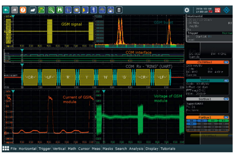
Invest in a decent benchtop or handheld spectrum analyzer for EMI testing. It doesn’t have to be top-of-the line, so an inexpensive FPC-1500 spectrum analyzer (5 kHz to 3 GHz options range) with ELEKTRA software will work fine. It also has a vector network analyzer and an independent signal source, which can be very useful to replicate and isolate problems. In many cases, the RTO-2000 oscilloscope will also work well, as it correlates what’s happening in other areas of the system, such as the power supply, to what’s going on with RF and EMI (Figure 2).
To start, set up the equipment for the expected range of frequencies and get various-sized H-field and E-field probes. Start “big” and then when an unexpected emission is detected, use smaller probes until the exact location is identified and deal with the problem before it becomes a liability. It’s often a case of adding more shielding or putting a filter in place, adding decoupling capacitors, or rerouting an antenna wire or pc board trace.
Conclusion
RF modules accelerate the time-to-connect when it comes to IoT devices and if properly designed and supported, form an expedient solution to the problem of RF connections. However, they don’t take developers fully out of the woods: the system itself still needs to be certified as meeting FCC, CE and CISPR requirements for EMI/EMC and RF emissions. Fortunately, much of this debugging can be performed cost-effectively at the bench, before sending a device off to a full-scale certification house.
Rich Markley is Product Manager for Rohde & Schwarz’s Value Instruments. In his current role, Rich is responsible for providing voice-of-the-customer input for all distribution products in North America. Rich has had previous roles in product planning, sales management and technical support for oscilloscopes and logic analyzers. Rich holds a BSEE from Kansas State University and a Master of Business Administration from the University of Colorado.


