
Smart World of IoT ? Smart System-Level Power Management for Smart Devices
June 11, 2019
Story

In this column, we'll take a look at controlling power at a system level, including that of the external peripherals and the regulator.
Last time, we explored the use of advanced power modes and integrated peripherals to optimize power consumption. In this column, we’ll take a look at controlling the power at a system level, including that of the external peripherals and the regulator.
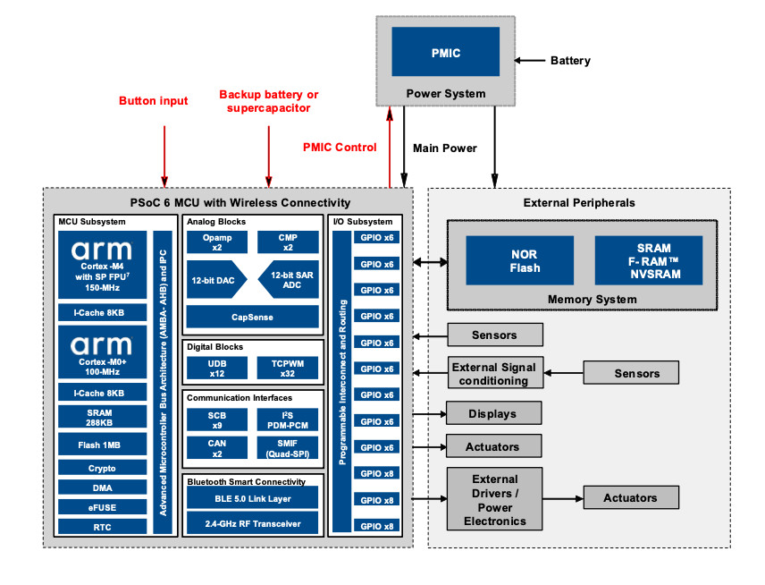
As explained in the previous column, 1) flexible and granular power modes, 2) specialized peripherals that are capable of operating in low power modes while being independent of the CPU, and 3) programmable analog and digital logic can help optimize the power of a Programmable System on Chip (PSoC). However, at the system level, there are additional peripherals that are connected to the PSoC, which also draw power and contribute to the battery drain of an IoT node. Figure 1 shows an example.

For optimizing power consumption at a system level, the power draw of these components must be controlled as well. Many peripherals, such as memories and sensors, come with an option to shut them down when their use is not required. This is done using a “shutdown” pin or a command over standard communication interfaces. However, there are scenarios in which this is not possible. Let’s take an example from the previous column - a DC signal chain in which a bridge sensor is interfaced with the ADC of the PSoC via internal opamps. The bridge sensor is a passive collection of four impedances. As such, it always draws power from the reference supply, even when the peripherals interfaced with it are turned off. A slight modification of the design using flexible GPIOs and internal logic, however, resolves this problem.
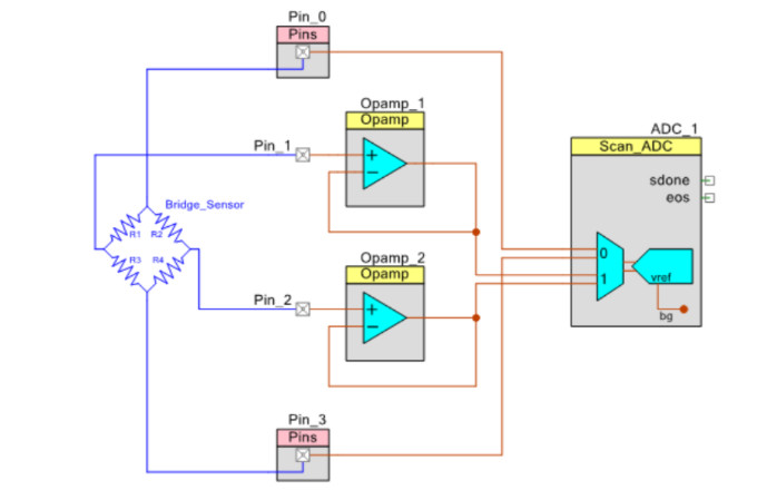
As Figure 2 shows, the bridge is now powered via GPIOs. This also provides an analog connection to the ADC for measuring the bridge excitation voltage and compensating for it. The bridge is powered when Pin_0 is at logic high, and Pin_3 is at logic low. When the bridge measurement is no longer required, in addition to turning off the internal blocks, this can also eliminate the current flow through the bridge sensor by making Pin_0 and Pin_3 at logic high impedance states.
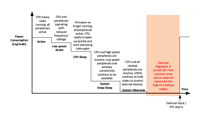
Not all external peripherals can be powered from the PSoC, and some may lack a “shutdown” pin or command altogether. These peripherals draw power from the supply continuously. In most cases, the power supply will have a power-management IC (PMIC) that supplies regulated power to the PSoC as well as the external peripherals. The regulator itself consumes power while being active. In addition to the core’s power consumption in low power modes, idle power of external peripherals and the regulator determine the lowest power consumption that can be achieved by the system. To get the best efficiency, turn the regulator off. The system can then drop into a “backup” domain to maintain an internal real-time clock (RTC) and wake on an external event such as a button press. Figure 3 shows the power mode transition diagram from the previous column modified to include this state.
The backup domain adds an “always on” functionality using a separate power domain supplied by a backup supply such as a battery or supercapacitor (see Figure 4). The backup domain contains a real-time clock (RTC) with an alarm feature, supported by a watch crystal oscillator (WCO) and PMIC control. Power to the backup domain is automatically switched between the main supply and backup supply. The backup supply is typically connected to an independent battery such as a coin cell or a supercapacitor. In the case of the supercapacitor, it is charged while the regulator and rest of the system are active.
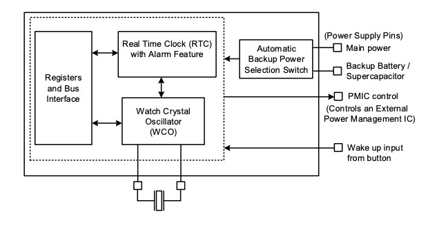
When the entire system needs to enter the lowest power state achievable, the system can instruct the PMIC to shut down. The PMIC, external peripherals, and internal peripherals (except the ones that run from the backup supply) are turned off. The system can wake up from this state using one of the two options – an internal RTC alarm event or an external pin input. Utilizing a backup domain significantly enhances the battery life of an IoT system while making other power options such as energy harvesting, viable.
Energy harvesting is the process by which energy is derived from the operating environment such as light, heat and mechanical energy. From a system-level perspective, energy harvesting could be a game-changing alternative to always drawing power from batteries. Energy harvesting is viable when a tiny amount of power is required for ultra-low energy systems. Solar modules are the most popular energy harvesting solution since they are readily available, easy to use, and low cost. However, with wearables such as smart shoes that are exposed to motion, piezoelectric and electromagnetic kinetic energy harvesting become attractive as they can generate large amounts of power with higher voltages. A thermoelectric generator is an excellent option in industrial applications for generating power from heat.
Although energy harvesting provides “free” energy, it requires carefully designed electronics to provide a constant supply to the IoT node from a varying energy source. More importantly, leakage should be minimized. Utilizing a backup domain puts the system into a minimal leakage state that can still maintain the ability to wake up on timed events and external inputs.
Innovative power management technology solutions enhance the performance and reliability of IoT systems. We will continue to explore more innovated solutions to make IoT devices even smarter in the upcoming column series.
Jaya Kathuria Bindra works as an Applications Manager at Cypress Semiconductor Corporation where she is managing the Embedded Applications Group and Solutions Development using the PSoC and WiFi/BT platform. She has 15+ years of experience in the Semiconductor Industry. She earned her executive management credential from IIM, Bangalore and holds a bachelor’s degree in Electronics Engineering from the Kurukshetra University.
Nidhin MS works as a Staff Applications Engineer at Cypress Semiconductor Corporation. He has seven years of technical experience with analog, power electronics, touch sensing, embedded computing and connectivity and holds a bachelor’s degree in Electronics and Communication Engineering.


