
Robust Ethernet Physical Layer Solutions for Time Critical Communications in Harsh Industrial Environments
February 27, 2020
Story
Industrial systems are increasingly adopting Ethernet connectivity to solve manufacturers? key Industry 4.0 and smart factory communication challenges.
Why Ethernet in Industrial Applications?
Industrial systems are increasingly adopting Ethernet connectivity to solve manufacturers’ key Industry 4.0 and smart factory communication challenges. These challenges include data integration, synchronization, edge connectivity, and system interoperability. Ethernet-connected factories enable higher manufacturing productivity, and more flexible and scalable manufacturing by enabling connectivity between information technology (IT) and operating technology (OT) networks. This allows all areas of the factory to be monitored and controlled on a single, seamless, secure, and high bandwidth network that supports time critical communications.
Scaled computing and a robust communications infrastructure are the lifeblood of the connected factory. Today’s networks struggle with increasing traffic loads and interoperability challenges across myriad protocols that require complex, power hungry gateways to translate traffic throughout the factory. Industrial Ethernet solves these interoperability issues on a single network by delivering critical deterministic performance seamlessly to the edge of the factory. Historically, there has been an issue with a lack of available Ethernet physical layers (PHYs) designed specifically for robust industrial environments. Designers of industrial communications equipment have had to make do and compromise for far too long with standard, consumer-grade Ethernet PHYs developed for the mass market. In the age of Industry 4.0, where the number of edge nodes is accelerating and determinism is vital to achieving the connected factory, enhanced, industrial-grade Industrial Ethernet PHYs are critical.
IT vs. OT Ethernet Connectivity
Ethernet has long been used as the communications choice of the IT world, given that its advantages include a well-supported, scalable, flexible, and high bandwidth communication solutions. It also has the interoperability benefits that come with being an IEEE standard. However, one key challenge in bridging the IT and OT networks and enabling seamless connectivity based on Ethernet technology is deployment in harsh industrial environments where time critical connectivity is required.
Industrial Ethernet Application and Ethernet Deployment Challenges
A connected motion application based on Industrial Ethernet connectivity for a smart factory is shown in Figure 1. Multiaxis synchronization and precision motion control are critical to high quality manufacturing and machining within smart factories. Increasing demands on production throughput and output quality are driving the need for faster response times and higher precision from servo motor drives. This improved system performance requires even tighter synchronization of servo motor axes used within the end equipment. Real-time 100 Mb Ethernet is widely used in motion control systems today. However, the synchronization only involves data traffic between the network master and slaves.
Networks need to enable synchronization across the boundary of the network into the application from sub-1 μs right down to the PWM outputs within the servo motor control. This improves machining and production accuracy in multiaxis applications such as robotics and CNC machines based on higher data rate gigabit Industrial Ethernet, with IEEE 802.1 time sensitive networking (TSN). This enables all the devices to be connected onto one high bandwidth converged network with real-time Industrial Ethernet protocols for edge-to-cloud connectivity.
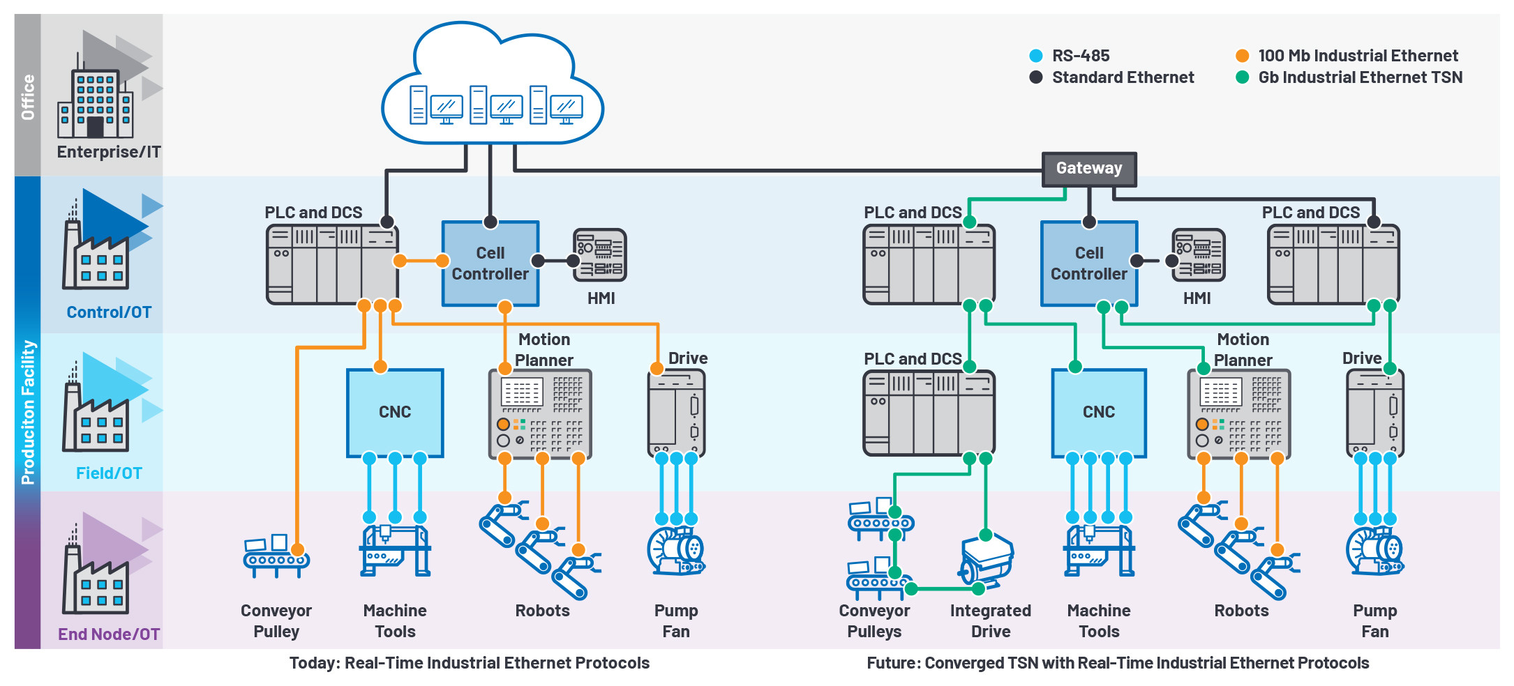
Figure 1. Connected motion applications enabled by Industrial Ethernet.
In an industrial environment, robustness and high ambient temperatures are major challenges for networking installers deploying Ethernet. Long cable runs are surrounded by high voltage transients from motors and production equipment potentially corrupting data and damaging equipment. To successfully deploy Industrial Ethernet, as shown in Figure 1, there is a requirement for an enhanced Ethernet PHY technology that is robust and low power with low latency in a small package that can operate in a noisy and high ambient temperature environment. This article will now discuss the challenges of deploying Ethernet PHY solutions in connected factories.
What Is an Industrial Ethernet Physical Layer?
An Industrial Ethernet PHY is a physical layer transceiver device for sending and receiving Ethernet frames based on the OSI network model. In the OSI model, Ethernet covers Layer 1 (the physical layer) and part of Layer 2 (the data link layer) and is defined by the IEEE 802.3 standard. The physical layer specifies the types of electrical signals, signaling speeds, media, and network topologies. It implements the Ethernet physical layer portion of the 1000BASE-T (1000 Mbps), 100BASE-TX (100 Mbps over copper), and 10BASE-T (10 Mb) standards.
The data link layer specifies how communications occur over the media, as well as the frame structure of messages transmitted and received. This simply means how the bits come off the wire and into a bit arrangement so that data can be extracted from the bit stream. For Ethernet, this is called media access control (MAC), which is integrated into a host processor or an Ethernet switch. See fido5100 and fido5200 as two examples of ADI’s embedded, two-port Industrial Ethernet embedded switches for layer 2 connectivity that supports multiprotocol, real-time Industrial Ethernet device connectivity.
Ethernet Physical Layer Requirements for Industrial Applications
1: Power Dissipation and High Ambient Temperature
Ethernet connected devices in industrial applications are often housed in sealed IP66/IP67 enclosures. IP ratings refer to how resistant an electrical device is to water, dirt, dust, and sand. The first digit after IP is the rating that the IEC assigned a unit for its resistance to solids. In this case, six, which means no harmful dust or dirt seeped into the unit after being in direct contact with the matter for eight hours. Next, we have the water resistance ratings six and seven. Six means protection from water projected in powerful jets, while seven means that the device can be submerged in up to one meter of fresh water for 30 minutes.
With these types of sealed enclosures, power dissipation and high ambient temperature are two major challenges for Ethernet PHY devices due to the reduced thermal conduction capability of these enclosures. To deploy Industrial Ethernet, Ethernet PHY devices with a high ambient temperature operation up to 105°C and very low power dissipation are required.
Typical Industrial Ethernet networks are deployed in line and ring topologies. These network topologies have reduced wiring length compared to star networks and have a redundant path in the case of a ring network. Each device connected to a line or ring network requires two Ethernet ports to pass Ethernet frames along the network. Ethernet PHY power dissipation becomes more critical in these use cases, as there are two PHYs per connected device. Gigabit PHY power consumption has a major impact on the overall power dissipation and a PHY with low power consumption allows more of the available power budget for the FPGA/ processor and Ethernet switch in the device.

Figure 2. Low power Industrial Ethernet PHY devices.

Figure 3. Ethernet PHY latency in Industrial Ethernet networks.
Let’s look at the example on Figure 2, where we have a device with a power dissipation budget of 2.5 W. It includes an FPGA, DDR memory, and an Ethernet switch that requires a budget of 1.8 W. This leaves just 700 mW of available power dissipation budget for two PHYs. To meet the device thermal requirements, a Gb PHY with <350 mW power dissipation is required. There are limited PHY options available today that meet this power dissipation target.
2: EMC/ESD Robustness
Industrial networks may have cable runs of up to 100 m in harsh factory conditions with high voltage transients from production equipment noise and the potential for ESD events from equipment installers and operators are commonplace. Robust physical layer technology for successful deployment of Industrial Ethernet are therefore essential.
Industrial equipment typically needs to pass the following EMC/ESD IEC and EN standards:
-
IEC 61000-4-5 surge
-
IEC 61000-4-4 electrical fast transient (EFT)
-
IEC 61000-4-2 ESD
-
IEC 61000-4-6 conducted immunity
-
EN 55032 radiated emissions
-
EN 55032 conducted emissions
The cost associated with product certification to these standards is high and it is common for new product introductions to be delayed if a design iteration is required to meet any one of these standards. Significant new product development cost and risk can be reduced by using PHY devices that have already been tested to the IEC and EN standards.
3: Ethernet PHY Latency
For applications that require real-time communications, as in Figure 1, where precise control of motion is paramount, PHY latency is an important design specification because it is a critical part of the overall Industrial Ethernet network cycle time. The network cycle time is the communication time required by the controller to both collect and update the data of all devices. Lower network cycle time allows for higher application performance in time-critical communications. A low latency Ethernet PHY helps achieve a minimum network cycle time and allows more devices to be connected to the network.
As line and ring networks require two Ethernet ports to transmit data from one device to the next, Ethernet PHY latency has double the impact with two ports per device (data in port/data out port), see Figure 3. A 25% PHY latency reduction on a network of 32 devices (64 PHYs) the impact of this reduced Industrial Ethernet PHY latency is significant, both to the number of nodes that can be connected and the performance (cycle time) of that Industrial Ethernet network.
4: Ethernet PHY Data Rate Scalability
It is also important to have Industrial Ethernet PHY devices that support different data rates: 10 Mb, 100 Mb, and 1 Gb. Connections between PLCs and motion controllers require high bandwidth, gigabit (1000BASE-T) TSN Ethernet connectivity. Field-level connectivity is based on Ethernet connectivity running Industrial Ethernet protocols on 100 Mb (100BASE-TX) PHYs. For end node/edge device connectivity, there is a new physical layer standard completed under IEEE 802.3cg/10BASE-T1L that will enable low power Ethernet PHY technology on single twisted-pair cables at 10 Mb bandwidth up to a distance of 1 km and can be used in intrinsically safe applications in process control. See Figure 4 for process control Ethernet connectivity and the need for scalable Ethernet PHY data rates from PLC to end node actuators and field instruments.

Figure 4. Process control, seamless edge-to-cloud connectivity.
5: Solution Size
As Ethernet technology proliferates toward the edge of industrial networks, the size of the connected nodes gets smaller. Ethernet connected sensors/actuators can have very compact form factors and therefore require PHYs in small packages developed for industrial applications. LFCSP/QFN packages with 0.5 mm lead pitch are proven to be robust, do not require expensive PCB manufacturing flows, and have the advantage of an exposed paddle underneath for increased power dissipation for high ambient temperature operation.
6: Product Longevity
Product lifetime availability is a concern for industrial equipment manufacturers because their equipment often remains active in the field for more than 15 years. This means product obsolescence is a very costly and time-consuming product redesign activity. Industrial Ethernet PHY devices must have long product life availability, something often not supported by suppliers of consumer, mass market, Ethernet PHYs.
Summary of Industrial Ethernet PHY Requirements for Robust Industrial Ethernet Applications
Table 1. Consumer vs. Industrial Ethernet PHY Requirements

Table 2. ADIN1200 and ADIN1300 Features

Table 3. ADIN1300 Robust Industrial Ethernet Gb PHY EMC/ESD Robustness Testing

ADIN1300: EMC/ESD functional performance classification:
Class A
-
No link drop.
-
No more than two consecutive lost or error packets.*
-
System must function normally with no errors post stress and without user intervention.
Class B
-
No link drop.
-
Lost and error packets allowed.
-
System must function normally with no errors post stress and without user intervention.
Class C
-
The link drops during testing and/or the system requires user intervention. For example, reset or power cycle to recover normal operation post the stress test.
-
Note that functional test software cannot determine if problem packets are consecutive.
Industrial Ethernet PHY Technology
To meet the needs of industrial designers, semiconductor companies have developed Industrial Ethernet PHYs designed to operate reliably in harsh industrial conditions over extended ambient temperature range up to 105°C and ensure long product lifetimes for new products developed for industrial applications. For example, the ADIN1300 and ADIN1200 from Analog Devices were developed specifically address the challenges of industrial applications, including:
-
Enhanced link loss detection that detects a link loss in <10 µs
-
A requirement for real-time Industrial Ethernet protocols (for example, EtherCAT®)
-
Start of packet detection for IEEE 1588 time stamp
-
Required for accurate timing across the network
-
Enhanced ESD protection on the MDI pins
-
ESD robustness on the RJ-45 connector
-
PHY power up time, <15 ms
-
Time from when power is good to management interface/registers available
-
On-chip power supply monitors
-
Improved system-level robustness on power up
See Table 2 for a summary of ADIN1200 and ADIN1300 Industrial Ethernet PHY features.
The ADIN1300 is the industry’s lowest power, lowest latency, smallest package size, 10 Mbps/100 Mbps/1000 Mbps Industrial Ethernet PHY that has been extensively tested for EMC and ESD robustness and supports extended ambient temperature operation up to 105°C. The ADIN1300 PHY has been tested to EMC/ ESD standards as shown in Table 3. By using Ethernet PHY technology that has been extensively tested to IEC and EN standards, the cost and time associated with product compliance testing and certification can be significantly reduced.

Figure 5. ADIN1200 with fido5200 for multiprotocol, real-time Industrial Ethernet device connectivity.

Figure 6. ADIN1300 and ADIN1200 customer evaluation boards and software GUI.
The ADIN1200 low power, 10 Mbps/100 Mbps, robust Industrial Ethernet PHY has been extensively tested for EMC and ESD robustness and supports extended ambient temperature operation up to 105°C. The ADIN1200 with fido5200 enables a system-level solution for multiprotocol real-time Industrial Ethernet devices connectivity supporting Profinet®, EtherNet/IP™, EtherCAT, Modbus TCP, and Powerlink for embedded two-port device connectivity as shown in Figure 5.
Support for Beckhoff EtherCAT and EtherCAT G Industrial Ethernet Protocols
The ADIN1200 PHY meets all the requirements for EtherCAT Industrial Ethernet protocol and is included in the EtherCAT PHY selection guide. The ADIN1300 PHY meets all the requirements for EtherCAT G Industrial Ethernet protocol and is included in the EtherCAT G PHY selection guide. For further details, see Beckhoff’s Application Note—PHY Selection Guide.
Customer Support
Customer evaluation boards are available for both the ADIN1300 and ADIN1200, along with a software GUI for quick evaluation. See ADIN1300 and ADIN1200 product pages on analog.com for a video tutorial on the application boards’ software GUI features. Figure 6 shows the application boards and the software GUI.
Summary
To enable seamless connectivity of the IT and OT networks and unlock the value of Industry 4.0, enhanced physical layer technology designed for industrial application is a key design choice. Robust Industrial Ethernet PHYs technology that solves the challenges of power, latency, solution size, 105°C ambient temperature, robustness (EMC/ESD), and long product lifetime are the foundation of the connected factory. To address the challenges outlined in this article, Analog Devices has recently released two new robust Industrial Ethernet PHYs, the ADIN1300 (10 Mbps/100 Mbps/1000 Mbps) and ADIN1200 (10 Mbps/100 Mbps/1000 Mbps)
For more information on the ADI Chronous™ portfolio of Industrial Ethernet solutions and how it is accelerating real-world Industrial Ethernet networks, please visit analog.com/Chronous.
About the Author
Maurice O’Brien is the strategic marketing manager for industrial connectivity at Analog Devices. He is responsible for the strategy supporting Industrial Ethernet connectivity solutions for industrial applications. Prior to this role, Maurice spent 15 years working in applications and marketing roles in power management with Analog Devices. He has a B.Eng. degree in electronic engineering from the University of Limerick, Ireland. He can be reached at [email protected].


