
Rarely Asked Questions: Enabling Battery-less Applications with Wireless Power
October 01, 2020
Story
My application doesn't have a battery. Is it possible to power it wirelessly?
Question:
My application doesn’t have a battery. Is it possible to power it wirelessly?

Answer:
Yes, sure—a simple integrated nanopower solution originally designed for energy harvesting is available.
A wireless power transfer (WPT) system is composed of two parts separated by an air gap: transmitter (Tx) circuitry with a transmit coil, and receiver (Rx) circuitry with a receive coil (see Figure 1). Much like in a typical transformer system, ac generated in the transmit coil induces ac in the receive coil via a magnetic field. However, unlike in a typical transformer system, the coupling between the primary (transmitter) and secondary (receiver) is typically very low. This is due to the nonmagnetic material (air) gap.
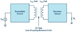
Figure 1. Wireless power transfer system.
Most wireless power transfer applications in use today are configured as wireless battery chargers. A rechargeable battery resides on the receiver side and is charged wirelessly whenever in the presence of a transmitter. After charging is complete, and when the battery is subsequently taken off of the charger, the rechargeable battery then powers the end application. Downstream loads can connect either directly to the battery, indirectly to the battery through a PowerPath™ ideal diode, or to the output of a battery-powered regulator integrated into the charger IC. In all three scenarios (see Figure 2), the end application can run either on or off the charger.
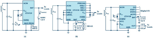
Figure 2. Wireless Rx battery chargers with downstream loads connected to a) a battery, b) a PowerPath ideal diode, and c) a regulator output.
But what if a particular application does not have a battery at all, and instead what is desired is just providing a regulated voltage rail when wireless power is available? Examples of such applications abound in remote sensors, metering, automotive diagnostics, and medical diagnostics. For example, if a remote sensor does not need to be continuously powered, then it doesn’t have to have a battery, which would either need to be replaced periodically (if it is a primary cell) or charged (if it is rechargeable). If that remote sensor only needs to give a reading when the user is in the vicinity of it, then it can be wirelessly powered on demand.
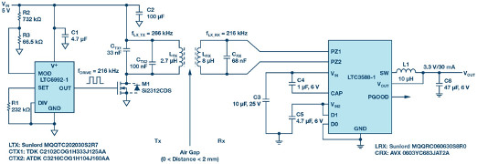
Figure 3. WPT employing the LTC3588-1 to supply a regulated 3.3 V rail.
Enter the LTC3588-1 nanopower energy harvesting power supply. Although originally designed for energy harvesting (EH) applications powered from a transducer (for example, piezoelectric, solar, etc.), the LTC3588-1 can also be used for wireless power. In Figure 3, a complete transmitter plus receiver WPT solution using the LTC3588-1 is shown. On the transmitter side, a simple open-loop wireless transmitter based on the LTC6992 TimerBlox® silicon oscillator is used. For this design, the drive frequency is set at 216 kHz, which is below the LC tank resonant frequency of 266 kHz. The exact ratio of fLC_TX to fDRIVE is best determined empirically with the goal of minimizing switching losses in M1 due to zero voltage switching (ZVS). Design considerations on the transmitter side with respect to coil selection and frequency of operation are no different than those for other WPT solutions: that is, there is nothing unique to having an LTC3588-1 on the receiver side.
On the receiver side, the LC tank resonant frequency is set equal to the drive frequency of 216 kHz. Because many EH applications require ac to dc rectification (just like WPT), the LTC3588-1 already has this built-in, allowing the LC tank to connect directly to the LTC3588-1’s PZ1 and PZ2 pins. Rectification is wideband: dc to >10 MHz. Similar to the VCC pin on the LTC4123/LTC4124/LTC4126, the VIN pin on the LTC3588-1 is regulated to a level appropriate for providing power to its downstream output. In the case of the LTC3588-1, the output is that of a hysteretic buck dc-to-dc regulator instead of a battery charger. Four pin-selectable output voltages: 1.8 V, 2.5 V, 3.3 V, and 3.6 V are available with up to 100 mA of continuous output current. The output capacitor can be sized to provide higher short-term current bursts provided that the average output current does not exceed 100 mA. Of course, realizing the full 100 mA output current capability depends on having an appropriately sized transmitter, coil pair, and sufficient coupling.
If the load demand is less than the available wireless input power can support, the VIN voltage will increase. Although the LTC3588-1 integrates an input protective shunt that can sink up to 25 mA if the VIN voltage rises to 20 V, this function may be unnecessary. As the VIN voltage rises, the peak ac voltage on the receiver coil does as well, and this corresponds to a drop in the amount of ac deliverable to the LTC3588-1 as opposed to simply circulating in the receiver tank. If the open circuit voltage (VOC) of the receiver coil is reached before VIN rises to 20 V, the downstream circuit is protected with no wasted heat in the receiver IC.
Test results: For the application shown in Figure 3 with a 2 mm air gap, the measured max deliverable output current at 3.3 V was 30 mA and the measured no load VIN voltage was 9.1 V. For a near-zero air gap, the max deliverable output current increased to approximately 90 mA while the no load VIN voltage increased to only 16.2 V, well below the input protective shunt voltage (see Figure 4).
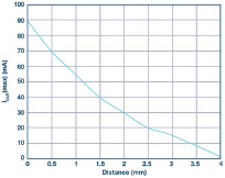
Figure 4. Max deliverable output current at 3.3 V for various distances.
For battery-free applications where a wireless power source is available, the LTC3588-1 provides a simple integrated solution for providing a low current regulated voltage rail with full input protection.
Mark Vitunic [[email protected]] is a design manager in the Power by Linear™ Group of Analog Devices. He officially joined ADI in 2017 as part of the acquisition of Linear Technology, where he had worked for the previous 19 years. Mark manages numerous project developments in North Chelmsford, MA and in Munich, Germany, with a focus on wireless power transfer, ultra low power ICs, energy harvesting, active battery balancing, and multichannel dc-to-dc regulators. Mark holds B.S. and M.S. degrees in electrical engineering from Carnegie-Mellon University and the University of California at Berkeley, respectively.


