
It's OK to be Trigger Happy When Using Digital Scopes
June 24, 2019
Blog

Oscilloscopes have had triggers almost since the beginning, but digital oscilloscope technology takes triggering to new heights. This enhanced functionality makes oscilloscopes much more useful.
Triggering is what really makes an oscilloscope useful. Triggering synchronizes an oscilloscope's display with the input signal, and by beginning the display at a consistent point on a waveform, provides users with a stable waveform display. Oscilloscopes have had triggers almost since the beginning, but digital oscilloscope technology takes triggering to new heights. This enhanced functionality makes oscilloscopes much more useful.
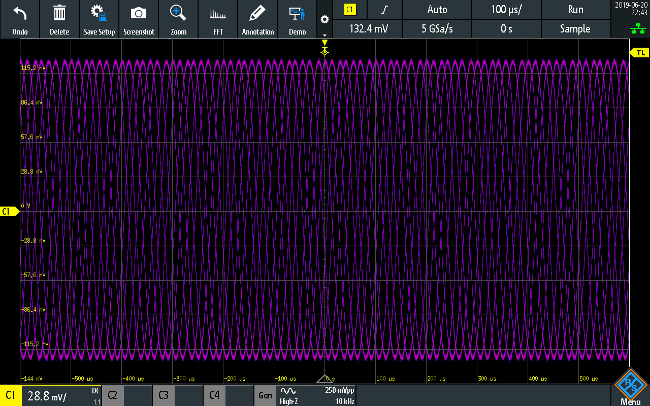
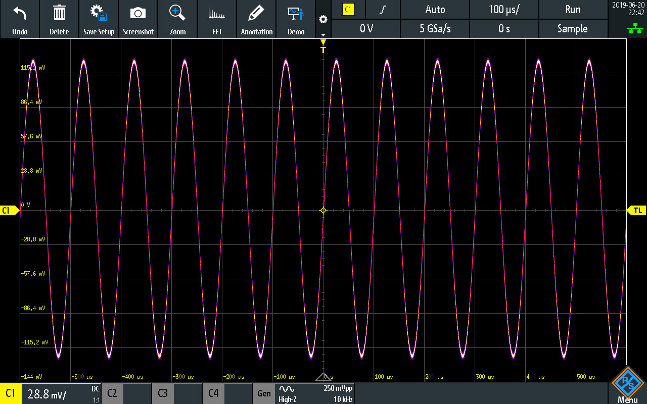
The most basic oscilloscope trigger function is triggering on a particular signal level and slope. That is to say that the scope begins displaying the input signal when the signal reaches a certain voltage and the voltage is either increasing (positive slope) or decreasing (negative slope). By starting the waveform display at the same point, the oscilloscope will display a stable waveform, especially if the waveform is a periodic one (Figure 1).
Digital oscilloscopes also have this basic trigger functionality but give users many more options than simply choosing a voltage level and slope. This gives users the ability to troubleshoot a wider range of problems than they could with analog scopes and do it more quickly and efficiently.
For example, with a digital oscilloscope, you can actually see what happens before the trigger point. This was impossible with an analog scope because the scope displayed the waveform only after the trigger point had been reached. Whatever happened before that was lost. A digital scope, however, is continually digitizing the input signal and recording it in memory, including what happened before the trigger. Usually, all you have to do is scroll the display back to see the signal before the input signal reached the trigger point.
In addition to this, digital scopes have a number of trigger functions that aren't found on analog scopes because analog scopes can't really analyze the input signal. Many digital scopes have a range of pulse triggering functions. For example, many scopes will allow you to trigger on:
- Pulses longer than a programmed reference time.
- Pulses shorter than a reference time.
- Pulses equal to a particular reference time (plus or minus a small tolerance).
- Pulses unequal to a particular reference time (plus or minus a small tolerance).
- Pulses whose pulse widths are between two reference times or pulses whose pulse widths are outside those reference times.
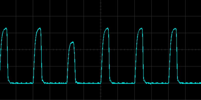
Another type of pulse trigger is the “runt” trigger. When this trigger is programmed, the scope will trigger when a pulse begins to go HIGH or LOW but fails to reach a valid HIGH or LOW level (Figure 2).
Digital scopes can also trigger on logic patterns. This is especially useful if you have four input channels or more, but even value-priced oscilloscopes can be extended with additional logic inputs. The scope can be programmed to trigger on a particular logic pattern or on a combination of channels. For example, you might want to trigger when a set of digital inputs are all TRUE, so you'd set the trigger to AND all those inputs together. Similarly, you might want to trigger when at least one of the inputs is TRUE, so you would set the trigger to OR the inputs. Some scopes also let you apply time limitations to these triggers. So like pulse triggering, you can set the scope to trigger only when a certain logic pattern occurs for longer or shorter than a particular time.
Many digital scopes now offer the ability to analyzer serial protocols, such as I2C, SPI or RS232/UARTS. Not only can these scopes decode bus traffic, they can also trigger on specific bus events or data. When troubleshooting an I2C bus, for example, you can trigger when:
- A frame starts.
- A frame stops.
- A frame restarts.
- A frame is not acknowledged.
- Various read/write conditions, such as when a bus master begins transmitting.
- Specific data are being sent over the bus.
All of these triggers are valuable in debugging both hardware and software problems. When it comes to digital scopes, being “trigger happy” is a good thing. Learning how to use these features can really help you up your game when using scopes and developing and troubleshooting hardware and software problems.
Rich Markley is Product Manager for Rohde & Schwarz’s Value Instruments. In his current role, Rich is responsible for providing voice-of-the-customer input for all distribution products in North America. Rich has had previous roles in product planning, sales management and technical support for oscilloscopes and logic analyzers. Rich holds a BSEE from Kansas State University and a Master of Business Administration from the University of Colorado.


