
Input/Output Considerations for Cockpit Displays
December 24, 2020
Blog
We discuss a special module, the I/O Manager, that takes inputs from peripherals like temperature sensors, fuel indicators, etc., and converts it to engineering units for a graphics generation module.
Have you ever thought how the pilots, sitting in the cockpit of a humongous airplane, know every detail about the aircraft like air speed, engine efficiency, fuel level, internal and external temperature, etc.? And interpret this information in a human-readable format?
In this article, we will discuss a special module, called the I/O Manager, that takes inputs from hardware peripherals like temperature sensors, fuel level indicators, etc., and converts that data into engineering units that are provided to a graphics generation module. The graphics generator module then adds some graphics along with X/Y coordinates and renders the result on the cockpit display.
Here is a top-level flow of how data from different peripherals reaches the cockpit display system.
Figure 1. Data flow from input sensors to the cockpit display.
What is the "I/O Module"?
The Input/Output Module is a discrete application that provides an interface from the physical airplane to other applications. The I/O application receives data from shared memory or the common data network, processes the data, and then makes it available for various applications residing on other system partitions via a shared memory.
Below are the common functions of I/O Manager:
- Receive, Validate(check incoming/outgoing messages) and transmit data
- Filtering
- Hysteresis (Up-down counts)
- Source selection
- Common Processing Unit
- Health monitoring
- Crosstalk mitigation
The I/O application also provides a service that allows local applications to transmit data to other applications hosted on other partitions.
Let's go through all of the I/O modules functions, one-by-one.
Receive. Validate. Transmit.
I/O operates by usiing thousands of well-organized parameters in multiple tables. Basically, it contains tables for Received Data (RX) and validated data and transmit data (TX).
All incoming data is received in RX tables. The I/O application takes this data, performs some operations, and then stores the results in availability and validity tables. Going further, I/O takes all valid data from the availability and validity tables and performs source selection on redundant sources and moves selected sources to the TX table for transmission.
Let's discuss these three stages in detail.
Receive Data
The I/O application retrieves data from the network or hardware device in the form of the ARINC 664 protocol. After fetching the data, it converts it to engineering units.
There is a status parameter associated with each value parameter. The I/O performs validity checking on received parameter values.
Figure 2. An I/O application fetches application data from the network and converts it to engineering units to be rendered as values on the cockpit display.
Availability and Validity Checking
The I/O application monitors the presence and validity of parametric input data and, using source selection, selects a valid source out of all redundant sources. It then provides the selected data to the display application.
Transmit Data
At the time of transmission, the I/O application loads parametric data into messages. It retrieves data from internal memory or from the display application.
Before transmitting the data, the I/O app checks the freshness of data and validates parameter values using its status parameter. After getting valid data using source selection, the I/O module packs parameter values and statues into messages as per the protocol and then transmits it onto the network.
What is the Use of Filtering?
The I/O module uses filtering to prevent any drastic change in the output. It will only gradually increase the output parameter values to keep plane movement smooth. For example, if a pilot makes a mistake during takeoff and increases the takeoff angle to 90 degrees, I/O filtering will increase the angle very slowly.
How Does I/O deal with Redundant Sources of an Input Value?
When aircraft is in the air it is almost completely disconnected from the support team on the ground in the event of equipment failure. So redundant hardware and software is always recommended for all types of input signals.
Here, the I/O module’s job is to select only one valid source for further processing. The I/O module performs source selection to select single valid and fresh source among multiple redundant sources coming from any hardware or software application. If all incoming redundant signals are valid, then the I/O module selects one signal based on pre-defined priority.
What is a Common Processing Unit?
Cockpit display software has many different applications designed to do specific tasks, including the Navigation Display (ND), Primary Flight Display (PFD), Multi-Function Display (MFD), Engine Indicating and Crew Alerting System (EICAS), and Heads-Up Display (HUD). All of these display applications publish some information to other display applications and consume some information published by other display applications, as needed.
The I/O module provides a special service to facilitate data transfer between all these display applications. It performs a common process to collect information from all display applications and keep the latest information ready for all applications to use. So now all of the displays only need to reach out to the I/O application to retrieve the information they need.
Which Communications Protocols Does the I/O Use?
Nowadays, modern technologies prefer using the A664 protocol over A429 protocols for data transmission. The I/O module also uses the A664 protocol to receive and transmit data from and to the common data network.
However, avionics is a collection of multiple devices and a few devices still use only the A429 data format. In such cases, the I/O module uses encapsulation to load A429 data into an A664 message and then send the A664 packet over the Aircraft network. On the receiving end (another partition), the I/O Manager receives A664 data from the Aircraft network, retrieves the A429 message from the A664 packet, and provides it to the application in question.
What is the Role of I/O in Device Health Monitoring?
The I/O runtime detects the health of various devices by continuously checking the status flags and freshness flags of signals coming from those devices. And if the I/O application encounters any issues in any of the signals coming from display applications or hardware devices like sensors, it waits for a particular cycle – if it does not get a valid value within a pre-defined timeout (known as hysteresis), the I/O module raises a fault to the heath monitoring system.
What is Crosstalk and How Does it Happen?
The process of sharing data between display applications like PFD, ND, EICAS, etc. is called crosstalk. Crosstalk within the same partition is done through the ARINC 653 protocol, but when the application wants to talk to another application residing on different partition, the I/O Manager helps it by sending data through the A664 protocol.
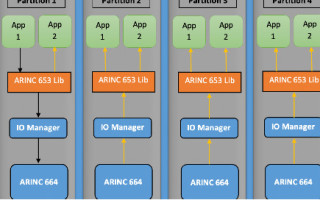
Figure 3 shows how crosstalk works within partition and between partitions.
Figure 3. Data transmission inside and between partitions.
In Figure 3, Application 1 in Partition 1 is transmitting data, while Application 2 in the same partition will receive data over the ARINC 653 port. Other applications receive data in A664 format with the assistance of the I/O manager.
When I/O publish data to other partition, it follows specific format for communication between partitions.
Conclusion
The I/O module is a multitasking application which receives data, checks if the data is valid or not, transmits the valid data, performs filtering on output values to avoid any accidents due to drastic changes made in signal values, performs source selection to select one valid source among multiple sources, helps applications share information with each other, and checks the health of various devices by continuously monitoring incoming signals. Overall, it is an all-in-one module that prevents invalid data from entering the system and makes the job of many other modules easier.
More information is available at www.einfochips.com.
About the Author
Akash Patel is a Senior Engineer at eInfochips, an Arrow Company. He has more than five years of experience in verification projects for Aerospace. He has bachelor’s degree in Electronics and Communications Engineering.


