
An Almost Pure DDS Sine Wave Tone Generator: Part 1
March 19, 2020
Blog
The test and verification of ac performance of high precision fast analog-to-digital converters (ADCs) with resolution better than 16 bits require a near perfect sine wave generator.
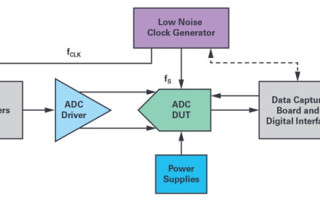
The test and verification of ac performance of high precision fast analog-to-digital converters (ADCs) with resolution better than 16 bits require a near perfect sine wave generator capable of covering a 0 kHz to 20 kHz audio bandwidth at least. Usually, expensive laboratory instruments are used to perform these evaluations and characterizations such as the audio analyzer AP27xx or APx5xx series from Audio Precision. Most of the time, modern high speed SAR and wideband sigma-delta (Σ-Δ) ADCs exhibiting 24 bits or more feature single-supply and full-differential inputs, and therefore require the signal source used for the DUT to be dc and ac accurate, while providing full differential outputs (180° out of phase). Similarly, the noise and distortion level of this ac generator should be much better than the specifications of these ADCs, resulting in a noise floor level well below –140 dBc and distortion lower than –120 dBc with an input tone frequency of 1 kHz or 2 kHz and up to 20 kHz according to most supplier specifications. A typical configuration of a typical bench test setup suited for high resolution wideband ADCs is illustrated on the Figure 1. The most critical component is the sine wave generator (single or multitone) and here a software-based direct digital synthesizer (DDS) can provide full flexibility with extremely fine frequency resolution and clock synchronization with the data acquisition system to perform coherent sampling to avoid leakage and FFT window filtering.
At a fraction of the cost of an audio precision analyzer, it is possible to design a very accurate sine wave generator based on the direct digital frequency synthesis (DDFS) principle, but implemented in software onto a floating-point DSP processor such as the SHARC processor. A reasonably fast floating-point DSP will meet real-time expectations and fulfill all the arithmetic and processing conditions to achieve the distortion and noise performance level set up by the most advanced SAR ADCs. Taking the benefit of a full-word data length architecture either in 32-bit or 64-bit fixed-point format for the NCO phase accumulation and extended precision floating-point DSP capabilities to execute the sine approximation function and the digital filters used to shape the spectrum, the quantization effects (rounding and truncation noise) are drastically reduced to be considered negligible compared to the digital-to-analog converter (DAC) imperfections used for the signal reconstruction.
Direct Digital Frequency Synthesis
The digital signal generator synthesizer patent filed in April 1970 by Joseph A. Webb1 described what could be considered as the basis of DDS mechanics to generate various types of analog waveforms, including sine waves, simply with the use of a few digital logic modules. Then, in early 1971, the frequently cited reference paper from Tierney et al.2 on direct digital frequency generation by deepening the DDS operation for quadrature generation as well as its limitations (word truncations and frequency planning) regarding the sampled systems theory was published. Practical realizations began to show up, mostly relying on discrete standard logic ICs such as the TTL 74xx or ECL 10K families. Less than 10 years later, fully integrated solutions came on the market introduced by companies like Stanford Telecom, Qualcomm, Plessey, and Analog Devices with the AD9950 and the AD9955. Designed for the best speed, power, and cost trade-off, the logic ICs’ architectures were based on a lookup table (LUT) to ensure the phase-to-sine amplitude conversion with limited phase, frequency, and amplitude resolutions. Today, DDS standalone integrated circuits are readily available while numerically controlled oscillators (NCOs) tend to be integrated in numbers in RF DACs like the AD9164 or the AD9174. Despite their impressive noise and linearity performance over a multiple GHz bandwidth, none of these devices are appropriate for the test of moderate speed, high resolution ADCs such as the LTC2378-20, the AD4020, or the AD7768.

Figure 1. Processing chain of a typical ADC (ac) test setup based upon the IEEE 1241 standard. The DDFS makes the whole measurement system fully digital with a lot of benefits including full flexibility and coherent sampling acquisition.
Compared to traditional PLL-based synthesizers, NCOs and DDSs are mostly known for their very fine frequency resolution, fast agility, and ease of sine/ cosine generation with perfect quadrature. They are also prized for their wide bandwidth coverage and dc accuracy. Their principle of operation is governed by digital signal processing and sampling systems theory, and their digital nature allows for fully digital and independent control of the phase, frequency, and amplitude of the output signals. The block diagram of Figure 2 depicts the architecture of a conventional DDS, which consists of three major functions:
- An N-bit phase accumulator;
- A phase-to-sine amplitude converter characterized by a W-bit truncated phase input word;
- A D-bit DAC and its associated reconstruction filter.
The phase accumulator is built around a simple N-bit adder combined with a register whose content is updated at the rate of the sampling clock FCLK with the input phase increment Δθ, also commonly called the frequency tuning word (FTW). The accumulator can periodically overflow and operates like a fractional divider between the sampling or reference clock FCLK and the DDS output frequency FOUT, or like a gearbox with a divide ratio equal to:

The overflow rate gives the output frequency of the generated waveform such that:

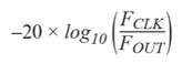
where 0 ≤ FTW ≤ 2N–1. Because of the divider effect, the contribution of the reference or sampling fS clock phase noise at the NCO output will be reduced by
The output of the phase accumulator register represents the current phase of the generated waveform. Each discrete accumulator output phase value is then translated into an amplitude sine or cosine data or sample thanks to the phase-to-sine or phase-to-cosine mapper engine. This function is usually accomplished by means of trigonometric values stored in a LUT (ROM) and sometimes by the execution of a sine approximation algorithm or a combination of the two. The output of the phase-to-sine amplitude converter feeds a DAC, which produces a quantized and sampled sinusoid before being filtered to smooth the signal and avoid spectrum aliasing. This amplitude quantization imposed by the DAC finite resolution puts a theoretical limit on the noise floor and the resulting signal-to-noise ratio (SNR) of the synthesizer. Moreover, as a mixed-signal device, the DAC exhibits a whole bunch of dc and ac nonlinearities due to its INL, DNL, slew rate, glitches, and settling time characteristics, which create spurious tones and reduce the overall dynamic range of the sine wave generator.
Practical sine waveform generator implementations based on the architecture of Figure 2 differ mostly by the phase-to-amplitude converter block, which is generally optimized for speed and power consumption rather than high precision because of the market orientation for digital radio applications. The simplest approach for the realization of the phase-to-sine amplitude converter is to use a ROM to store sine values with one-to-one mapping. Unfortunately, the length of the LUT grows exponentially (2N), with the width N of the phase accumulator and linearly with the wavetable data word precision W. Unfortunately, trade-offs consisting in the reduction of the accumulator size or truncating its output result in the loss of frequency resolution and a severe degradation of the SFDR. It is shown that spurs caused by phase or amplitude quantization follow a –6 dB/bit relationship. Since a large N is normally desired to achieve a fine frequency tuning, several techniques have been promoted to limit the ROM size while maintaining adequate spur performance. Simple compression methods are commonly used by exploiting the quarter wave symmetry of the sine or cosine function to reduce the phase argument range by 4. For further range reduction, brutal truncation of the phase accumulator output is the de facto method, although it does introduce spurious harmonics. Despite that, this approach is always adopted because of the fine frequency resolution requirements, memory size, and cost compromise. Various angular decomposition methods have been suggested to lower the memory requirements with LUT-based methods. Combined with amplitude compression using various types of segmentation, linear, or polynomial interpolation, the idea is to accurately approximate the first quadrant of the sine function or over the [0, π/4] interval in the case of I/Q synthesis for which both sine and cosine functions are needed. Similarly, complex signal generation with no ROM LUT is efficiently supported by angle rotation-based algorithms just calling for shift and add operations in a successive approximations scheme. This method, represented by the popular CORDIC, is generally faster than other approaches when a hardware multiplier is not available or when the number of gates required to implement the functions should be minimized (in an FPGA or an ASIC) for speed or cost considerations. Conversely, when a hardware multiplier is available—as is always the case in a DSP microprocessor—table-lookup with interpolation methods and full polynomial calculations, such as Taylor-series expansion, Chebyshev polynomials are faster than CORDIC, especially when high accuracy is a must.
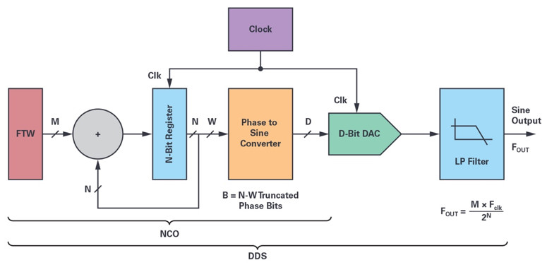
Figure 2. Main functional sections of an NCO and distinction with the complete direct digital synthesizer, which includes the reconstruction DAC and its associated AAF. The NCO section can be used to test or stimulate DACs.
In part 2 of this series, we’ll go into detail on how to implement a high precision NCO in software.
About the Author
Patrick Butler is a field applications engineer with Analog Devices’ south Europe sales organization, supporting the French global market and some ADEF customers. He has been with ADI since 1984, supporting the DSP building blocks ICs, as well as high speed converters. Previously, he worked as a design engineer in the ATE division of Schlumberger in Saint-Étienne, France for five years, and then occupied several application engineer and FAE positions at Matra-MHS in Nantes, AMD and Harris SC-Intersil. Today, his main hobby is collecting vintage sound components to build active, high efficiency horn loudspeaker-based systems with the help of his two sons.
1 Joseph A. Webb. U.S. patent US3654450 April 1970.
2 Joseph Tierney, Charles M. Rader, and Bernard Gold. “A Digital Frequency Synthesizer.” IEEE Transactions on Audio and Electroacoustics, Vol. 19, Issue 1, March 1971.


