
Accurate Measurement of Latency and Throughput of Time Sensitive Networks
February 01, 2019
Story

This article is on the IEEE standard IEEE802.1Q Time Sensitive Networking (TSN).
A few years ago, engineers in the automotive industry worked on improving the mechanical performance of clutch transmissions, exhaust systems and adding a turbocharger. Due to low data rates, CAN and CAN-FD functioned well for these applications. Today every vehicle shipped has an average of about 60 - 100 complex sensors, higher in the case of autonomous and electric vehicles.
Flexibility and reliability are the first call. Ethernet ensures flexibility and achieves bandwidth requirements. Unfortunately, it is insufficient for any reliability related applications because the data generated might be time critical for safety critical applications. Ethernet is non-deterministic with a degree of uncertainty in Quality of Service (QoS), potential packet losses and wide range latency.
Time Sensitive Networking (TSN) can effectively change the scenario with its traffic shaping protocol IEEE802.1Qbv. It improves the end-to-end latency, which guarantees constant latency for time-critical Control Data Traffic (CDT) and makes Ethernet deterministic. TSN is far more expensive than a simple CAN or CAN-FD implementation. Before investing in a TSN infrastructure, one should verify if the design is viable for the target application.
System Level Modeling is a good option. Here you build your design specification as a virtual model (rapid virtual prototype), simulate it on a computer and conduct trade studies. Bottlenecks in the design are identified with System Level Modeling before implementation. This ensures that all surprises are eliminated before integration.
VisualSim implements a System Level Modeling solution that contains the complete set of TSN protocols in accordance with the IEEE standards. In addition, some of the emerging requirements for clock alignment and QoS are also available. The TSN library support includes IEEE802.1Qbv, IEEE8201.Qbu, IEEE 802.3br, IEEE 802.1Qca, IEEE 802.1Qcc, IEEE 802.1Qci, IEEE 802.1QCB, IEEE 802.1Qch and IEEE 802.1AS protocols.
Modelers and architects use the VisualSim Graphical User Interface (GUI)-based building blocks to create and analyze their models. Parameters or design attributes can be changed to conduct timing and throughput studies and generate statistics. Due to the availability of pre-built libraries with configuration parameters, the users can simply instantiate the Nodes and Gateways without learning a new programming language. The TSN protocol libraries can be extended by the user to incorporate proprietary features.
We have implemented a system model of a complex network in VisualSim. The model contains a combination of CAN, CAN-FD, traffic generators to represent sensors, user-cases, TSN Gateways and Ethernet nodes. The model is shown in Figure 1. The key TSN parameters configured are guard band period, buffer size, Idle and send slope values, Ethernet overhead and sensor offset. The simulated output results for Latency and Credit are shown below. Latency plot shows the time taken from the sensor or ECU source using a CDT, AVB class A or B, or Best Effort frames to the destination ECU. The credit graph plots the SendSlope and IdleSlope values at each TSN Gateway. The graphs are shown in Figure 2 and 3.
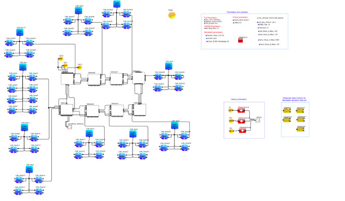
Each of the message frames is assigned a HashID, which is unique in the entire model. We have implemented an 8 Gateways architecture. Each Gateway has a few Ethernet interfaces for local Electronic Control Units and high-bandwidth sensor interface. In addition, each gateway is connected to one or more CAN-FD networks.
The entire model is configured using a variety of tables. The values in the table are extracted from CANdb and other standard configuration XML files. We make use of a table called Classification Table to store the type of Routing, parent Gateway, associated Hash ID for the message frames and parent CAN bus name. A table called ForwardingTable is used for forwarding the generated packets out to the destination and for assigning a Class type to each frame. The packets that have to go to CAN nodes at a different Gateway have to go through Ethernet interface on the Gateway. If a packet coming into the Gateway has its destination local to the Gateway, the packet is converted into the respective protocol and sent out on the local interface. All class types have Bandwidth allocated to it. The bandwidth allocation is obtained from the Priority BW table. The Gate Control List defines the time slices and associated classes.

In this Test case, we have assigned two time slots. For the first slot the Class Measurement Interval (CMI) is of 2 msec. This first part of the time slot is allocated to CDT frames. CDT frames are not assigned to the second time slot. A Maximum Interval Frame (MIF) of 5 is used. The remaining time is allocated for AVB Class A and B. First, Class A and then Class B frames are given the opportunity to transmit. This continues until they deplete their allocated Bandwidth, as shown in Figure 2 or complete transmitting the data. When there is no more Idle Slope or no more data to transmit, Best Effort Ethernet traffic can start transmitting. The Ethernet traffic is also assigned bandwidth by type of service. Any remaining bandwidth is given to type of service that is not assigned any bandwidth.
For the second time slot, CMI is 8 msec and MIF of 15000 is used. If the bandwidth allocated for AVB and BE is exhausted and there is time remaining, priorities with zero bandwidth are provided an opportunity to transmit. At the end of the defined time slots, a guard band of specified time is added to prevent overlapping and to send the last frame. The VisualSim library has implemented Time Aware Shaping (TAS), which ensures on each slot utilizing the maximum time and thus experiments with efficient use of resources.
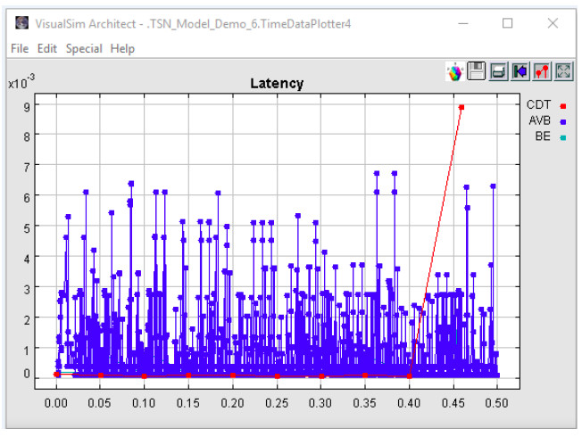
From the results graph, we see that a CDT frame had missed its time slot after 400msec and as such has a higher latency. The model we developed has 8 gateways, 8 high-speed Ethernet interfaces and 10 CAN networks. The entire model and test case were built using VisualSim and the automotive library, in two weeks.
By implementing a System Level Model as a virtual prototype in VisualSim, we were able to rectify critical design errors, determine the latency for each data stream, identify bottlenecks that could cause the CDT traffic to miss the deadline and assign the CAN networks to the Gateways. We also made changes to the Idle Slope periods to maximize the bandwidth allocation for the Class A and B. The large scale experimentation in system-level modeling helped us test out different network configurations and measure the effective throughput.
Tom Jose is an Application Specialist at ELC Labs, India. He holds a B.Tech degree in Electronics and Communication. Mr. Jose has been designing a variety of embedded systems and networking architectures. The technologies involved include networking protocols such as Time Sensitive Networking and CAN; embedded interfaces including PCI; SoC buses such as AXI and AHB and processors such as Cortex M7, Cortex R5 and RISC-V. He has presented at a number of industry conferences and has most recently published a paper titled, “Architecture Exploration of RISC-V Processor and Comparison with ARM Cortex A53” at the RISC-V International Conference. Mr. Jose has also done a project on implementing a low power, high efficiency Network on Chip routing algorithm.


