
A Simple Way to Measure Temperature Using One GPIO Digital Interface
October 12, 2020
Story

Question: How can I make an analog measurement if I only have a single GPIO left on the FPGA/microprocesser for my system?
Question: How can I make an analog measurement if I only have a single GPIO left on the FPGA/microprocesser for my system?
Answer: A voltage-to-frequency converter can be used instead of an analog-to-digital converter.
As the need for sensing capabilities becomes more prevalent in modern applications focused on machine health and other Internet of Things (IoT) solutions, so does the need for simpler interfaces with fewer I/Os and smaller device footprints. The density of devices connected to a single microprocessor or FPGA is continuing to increase. This is happening while application space, and as a result, the number of I/O pins can become constrained. In an ideal world, all applications would have an ASIC providing a small integrated solution. However, ASIC development is time consuming, costly, and doesn’t provide the flexibility to be repurposed for other uses. As a result, more and more applications are using microprocessors or small form factor FPGAs to get product development done in a timely and cost-effective manner. In this article, we will explore a temperature-to-frequency converter that can provide accurate temperature results while only using a single GPIO pin. It will also demonstrate how using a voltage-to-frequency converter can be adapted to a variety of sensing applications.
Motivation
Some sensor measurements, such as temperature, humidity, and barometric pressure, are inherently DC and don’t change at rates fast enough. Nor do they require resolutions accurate enough to warrant an ADC, and the design considerations that go along with it. Most ADCs require fast, accurate clock generation and timing, a stable voltage reference, a reference buffer with very low output impedence, and analog front-end circuitry to properly signal condition a transducer output before it can be digitally quantized and used by the system monitoring it. In the case of sensing ambient temperature, a discrete application might use a thermistor in a Wheatstone bridge whose output would then be gained up by an instrumentation amplifier and then fed into an ADC. This design is over-engineered and requires more space, power, and computation cycles necessary for an application where the measurement might only need to be made once every 15 seconds.
What alternative measurement solution can be used to reduce the number of components and complexity associated with an ADC signal chain, but still measure an analog voltage? The solution is a voltage-to-frequency converter, such as the LTC6990, configured in voltage-controlled oscillator (VCO) mode, can be used to measure an analog voltage without an ADC. In this example, the AD8494, a precision thermocouple amplifier, is configured as an ambient temperature sensor whose output voltage serves as the input to the LTC6990, resulting in a temperature-to-frequency converter signal chain.
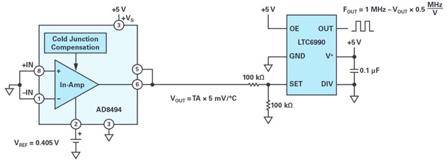
(Figure 1. The simple temperature-to-frequency converter.)
How to convert a temperature input to a frequency output
Today, many modern electronic appliances require an on-board temperature monitoring system. The method of converting analog signals to pulse-width modulated signals or digital signals is well documented. However, if the measurement solution would require an ADC, there are drawbacks associated with cost, accuracy, and speed. Typically, the more accurate the measurement, the more expensive the solution. This circuit delivers a low cost, versatile, and easily interfaceable solution whose accuracy can vary as determined by the needs of the temperature measurement system.
The AD8494 is a precision thermocouple amplifier, but it also can be used as an ambient temperature sensor by shorting its inputs to ground. The output is then defined as:

In this circuit where a unipolar supply is used, –VS = ground (0 V) and an offset voltage must be applied to the REF pin of the AD8494 in order to bias the output voltage above ground, even if ambient temperatures are negative.
The output voltage of the temperature sensor, VOUT, is defined as:

In VCO mode, the LTC6990 frequency output is defined as:
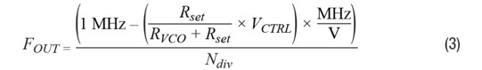
Since the output voltage of the AD8494 is VCTRL to the LTC6990, Equation 1 can be substituted for VCTRL in Equation 2, and setting RSET = RVCO yields the following:
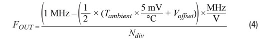
From here, Tambient can now be solved for. The voltage units cancel out, which yields Equation 5:

Okay, I have a frequency output. How is this useful?
The beauty of a frequency output is that you can use a single GPIO pin to get a sensor measurement. If the synchronous counter circuit in Figure 3 is used, then the rising edge of a clock will always be observed at its CLK_IN input. If the FOUT of the LTC6990 is used as the input clock, then the counter will increment every time a rising edge on FOUT is detected, creating a period counter. If the time interval between each measurement is constant, then the number of periods within a given time interval can be counted and frequency can be determined either by using floating point math or a lookup table. By dividing the acquisition time TAcquisition by the number of periods counted, we get the period of FOUT. Taking the inverse of this relationship results in Equation 6.
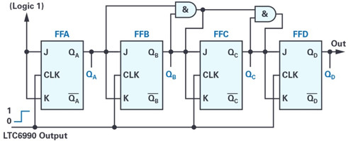
(Figure 2. A 4-bit synchronous counter with LTC6990 output as its clock input.)

The example Verilog code shows a function that can be used to count the number of periods by using a single GPIO input on an FPGA. The larger the acquisition period, the more accurate the measurement will be. In the case of the following code, a 16-bit counter is used to provide additional resolution. This also assumes the logic that controls the measurement acquisition time is performed at a higher level in the architecture.
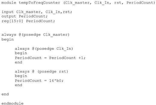
(Figure 3. Example Verilog code.)
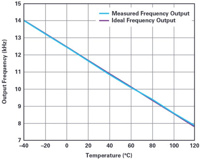
(Figure 4. Transfer function of the temperature-to-frequency converter.)
Conclusion
In this application, a new type of temperature-to-frequency converter is discussed. It provides an accurate, low cost method to measure temperatures. If the temperatures exceed the industrial range of –40°C to +125°C, a thermocouple can be installed at the inputs of the sensor. As a conclusion, the following plot shows the error of the measurement system. It demonstrates the linear relationship between the ambient temperature and the output frequency as well as the accuracy of the system. While this solution may not provide a very fine temperature resolution result, for applications where roughly ±2°C error is acceptable, this provides a cheap and simple interface for measuring temperature. Additionally, the concept of using a voltage-to-frequency converter can be adapted to measure other types of transducer outputs without the need for an ADC.
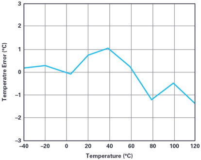
(Figure 5. Temperature error.)
References
“Fundamentals of the Electronic Counters.” Hewlett Packard, 1997.
Johansson, Staffan. “New Frequency Counting Principle Improves Resolution.” Proceedings of the 2005 IEEE International Frequency Control Symposium and Exposition, 2005.
Kamal, Ibrahim. “5 Hz to 500 kHz Frequency Meter.” IKA Logic, April 2008.
Synchronous Counter. ElectronicsTutorials, 2019.
About the Author
Chau Tran joined Analog Devices in 1984, where he works in the Instrumentation Amplifier Products (IAP) Group in Wilmington, MA. In 1990, he graduated with an M.S.E.E. degree from Tufts University. Chau holds more than 10 patents and has authored more than 10 technical articles. He can be reached at [email protected].
About the Author
Naveed Naeem joined Analog Devices in 2016 as a product test development engineer. Prior to joining ADI, he worked as an electrical engineer for an automotive sensors company for 3 years. His interests include sensor applications, analog-to-digital converters, audio applications, and software development. In 2013, he graduated with a bachelor’s degree in electrical and computer engineering from Worcester Polytechnic Institute. He can be reached at [email protected].


