What does an aggregator look like?
May 18, 2018
Story
The simplest description of an aggregator is that it is a self-contained computer system.
This is part five of a series. Read part four here.
I have suggested already that a smart phone can be seen as the poster child for an aggregator, so I’ll start there to describe the components of an aggregator. The simplest description of an aggregator is that it is a self-contained computer system. It has:
- A computer system
- A power management system
- A memory system
- Communication systems
The aggregator is a standalone system, but it can also be a subsystem in a larger system.
An aggregator can be designed using a printed circuit board (PCB) with discrete components, or in the form of a system on a module (SOM), or a system in a package (SiP), or a system on chip (SoC). Generally the decision on which of these forms it takes on is dependent on size and flexibility constraints more than cost and performance constraints. I’ve included a couple of figures to help describe what an aggregator looks like. The first, Figure 1, is a typical block diagram of an aggregator.
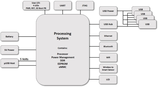
[Figure 1 | Typical block diagram of an aggregator.]
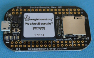
The second one, Figure 2, is a PCB-based processor system, which could easily be used as an aggregator. That PCB is the BeagleBoard.org Pocket Beagle. It is an tiny-yet-complete open-source “USB-key-fob computer.” It is based on a SiP device with a microprocessor from Texas Instruments, the AM3358.
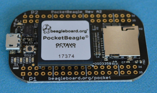
[Figure 2 | PocketBeagle with 21mm SiP processor system.]
What’s inside? Figure 3 presents two SiP devices with an ARM A8 with power management and a DRAM. The larger of the two is in a 27x27 mm package with a 400 ball BGA with a ball to ball spacing of 1.27 mm. The smaller of the two is in a 21x21 mm package with a 256 BGA with a ball to ball spacing of 1.27 mm. The smaller of the two SiP devices has, in addition to the components the larger has, a small EEPROM die in the lower right hand corner.
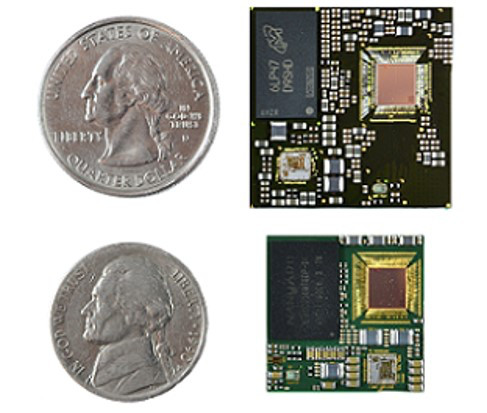
[Figure 3 | Comparison of the 27 and 21mm ARM based SiPs.]
In both of the two versions shown in Figure 3, the major components of an aggregator are included:
- The processor (upper right in both devices)
- The memory (DDR3 is in the upper left in both devices)
- The power management (lower left and lower right respectively)
- The necessary passive devices to make it all work (scattered throughout the two devices)
- A ball grid array to connect to the rest of the system (not shown as it is on the backside of the substrate)
For these two devices, the processor is the Texas Instruments 1 GHz ARM Cortex A8-based SoC, AM3358. It is in die form and wire-bonded to the substrate. Included is a variety of peripherals, inputs, outputs, and communication protocols. The memory device is a standard DDR3 packaged device. The power management (PMIC) is one from Texas Instruments.
Just as technology has allowed us to reduce the footprint of the aggregator, as shown in Figure 2, it will also allow us to reduce the footprint of its components. We are not far from the realization that the whole aggregator system will fit into a package the size of one of the devices shown in Figure 3. We will be able to shrink systems even further as we learn to improve on power efficiency and wireless communications.
Now for a question or two:
- In the two examples given the ball grid arrays are 400 and 256 balls with a spacing of 1.27 mm. In your system application, would you rather have more balls with closer spacing (e.g., 1 mm or 0.8 mm), or fewer balls and smaller overall footprint?
- What would be your first choice of a processor for an aggregator system?
- What would be your first choice for an operating system in an aggregator system?
Gene Frantz is Co-Founder and Chief Technology Officer at Octavo Systems.