
IoT over BLE in 10 minutes with Microchip Curiosity and MikroElektronika Clicks
June 16, 2017
Press Release
Goal: The following describes how to build a simple Internet of Things (IoT) data streaming application over Bluetooth Low Energy (BLE) using the Microchip Curiosity High Pin Count (HPC)...
Goal: The following describes how to build a simple Internet of Things (IoT) data streaming application over Bluetooth Low Energy (BLE) using the Microchip Curiosity High Pin Count (HPC) development board, MikroElektronika Bluetooth and gyroscope Clicks, and the MPLAB X integrated development environment (IDE). We begin by configuring Curiosity’s onboard 8-bit PIC16F18875 microcontroller (MCU) to receive orientation data from the MikroElektronika MIKROE-1379 GYRO Click using quick-start libraries recently added to the MPLAB Code Configurator (MCC). We proceed by modifying code from sample applications within MCC to instruct the MikroElektronika MIKROE-1715 BLE2 Click based on the Microchip RN4020 module to broadcast axis data from the GYRO Click. This data is received and displayed in an free Bluetooth scanner smartphone app.
Hardware required/cost:
- Microchip Curiosity HPC development board with PIC16F18875 MCU – $32.96 USD
- MikroElektronika MIKROE-1715 BLE2 Click – $30.60 USD
- MikroElektronika MIKROE-1379 GYRO Click – $25.50 USD
Software required (version):
- MPLAB X IDE (version 3.61 used)
- MPLAB Code Configurator (MCC) (version 3.26.2 used)
- MPLAB XC8 C compiler (version 1.42 used)
Cost estimate: $89.06 USD
Time estimate: 10 minutes
Difficulty level: Beginner
Setting up the project
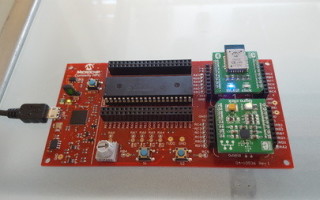
After downloading and installing the required software (installation instructions at http://www.microchip.com/curiosity), plug the MikroElektronika BLE2 and GYRO Clicks firmly into the mikroBUS headers on the Curiousity HPC development board. Connect one end of a USB 2.0 Mini cable to the Curiosity HPC USB connector and the other end to your desktop to power up your system. Green power (“PWR”) LEDs will illuminate on the Curiosity board and GYRO Click, along with a blue “wake” LED on the BLE2 Click (Figure 1).
DEVELOPER NOTE: The Curiosity HPC accepts both 3.3 V and 5 V power supplies, but the Mikroelektronika Clicks were only designed to accept 3.3; be sure the jumper next to Curiosity HPC’s power LED is set to 3.3 V before powering up the system so you don’t blow any components – not fun.

[Figure 1 ]
Fire up the MPLAB X IDE and start a New Project (For details on how to complete this process, see “Look ma, no code! PWM control in under 5 minutes with Microchip Curiosity development board and MPLAB Code Configurator“).
Configuring your system
A primer before diving into configuration is that Microchip engineers recently completed a “50 in 50” program in which they added quick-start library support for 50 MikroElektronika Click directly into MCC over 50 days. This really helps accelerate the development process (as you’ll find out), as MCC automatically generates code for various resources in a given MPLAB X project. In essence, the Click boards are treated like any other Microchip peripheral. Since completing the 50 in 50 program, Microchip has continued to add support for other MikroElektronika clicks.
Adding Click boards to your project
Once your new project is selected in the “Project Resources” window to the far left of the MPLAB X dashboard, open MCC. You are able to do this by clicking the MCC shield in the MPLAB X IDE navigation bar, or by selecting it from the “Tools > Embedded > MPLAB Code Configurator: Open/Close” dropdown menu (Figure 2).

[Figure 3 | ]
Once MCC is open several windows will appear that allow you to program the device with a few mouse clicks. The interface should have defaulted to the “Resource Management [MCC]” tab, and the “Project Resources” window should display with the “System Module” option selected. If not, select it. Now in the “Device Resources” window, scroll to the nested “Mikro-E Clicks” list, expand it, and then expand the nested “Sensors” and “Wireless Connectivity” lists (Figure 3). From there, double click on “Gyro” and “BLE2”, respectively, to add them to the project. Selecting them will also more information on the parts in the main MPLAB X viewing window.

[Figure 3 | ]
DEVELOPER NOTE: While the System Module is selected, ensure that the “Low-voltage programming Enable” checkbox is marked in the main System Module window (Figure 4); this is a requirement when programming 8-bit PIC MCUs within MPLAB X.

[Figure 4 | ]
An important observation on the power of MCC is available here, as navigating back to the “Project Resources” window you will find that not only have the two clicks been added to the project, but their required communication peripherals have been as well (Figure 5). These resources have also been added to the “Pin Manager” window, which you’ll use next.

[Figure 5 | ]
Pin configuration
In the Pin Manager window you’ll now find all of your devices and peripherals waiting to be configured to their respective pins. Pin locations are conveniently located on the sides of both of Curiosity HPC’s mikroBUS headers and both click boards, so all there is to do is transfer this information into the MCC Pin Manager. You can view the pin configuration for this project in Figure 6, or use the following list with descriptions to select the proper pins (Module/Function/Direction: Port – Purpose):
- BLE2/Cmd_Mldp/output: Port RC2 – For controlling the BLE2 Click’s RN4020 module when a Microchip low-energy data profile (MLDP) serial data service is used
- BLE2/Conn/input: Port RA1 – In its active-high state, this pin indicates that the BLE2 Click’s RN4020 module is connected to a remote device
- BLE2/Wake/output: Port RD0 – Indicates the sleep or wake state of the BLE2 Click’s RN4020 module
- EUSART/RX/input: Port RC7 – For communications from the BLE2 Click to the Curiosity HPC board (DEVELOPER NOTE: The input (RX) and output (TX) pins will be reversed in MCC from what’s displayed on the BLE2 Click board)
- EUSART/TX/output: Port RC6 – For communications from the Curiosity HPC board to the BLE2 Click (DEVELOPER NOTE: The input (RX) and output (TX) pins will be reversed in MCC from what’s displayed on the BLE2 Click board).
- MSSP1/SCL1/in/out: Port RC3 – For passing serial clock signals between the Curiosity HPC and GYRO Click over the I2C bus
- MSSP1/SDA1/in/out: Port RC4 – For passing serial data signals between the Curiosity HPC and GYRO Click over the I2C bus
- OSC/CLKOUT/output: None (DEVELOPER NOTE: N/A for this project)
- Pin Module/GPIO/input: Port RB4 – For enabling interrupts via the push button connected to pin S1
- Pin Module/GPIO/output: None (DEVELOPER NOTE: N/A for this project)
- Reset: Port RE4

[Figure 6 | ]
Changing clock frequency and renaming GPIO pins
At this point you need to increase the speed of the high-frequency internal clock of Curiosity HPC’s PIC16F18875 MCU to handle UART communications with the BLE2 Click, because the RN4020 module operates at a baud rate of 115,200 bits per second. To do this, navigate to the “System Module” window and change the “HF Internal Clock” field value from “4_MHz” to “16_MHz” using the dropdown arrow. Next, change the “Clock Divider” field value from “4” to “1” (Figure 7). The PIC16F18875 is now running fast enough to handle UART serial communications.

[Figure 7 | ]
Now it’s time to rename the GPIO pin to something more human friendly when we get into coding. Turn your attention to the Project Resources window and select “Pin Module” from the “System” dropdown. In the main MCC viewer window find the “RB4” pin and change the “Custom Name” field from “IO_RB4” to “S1” as shown in Figure 8 (which I chose just because that’s the connector label on the Curiosity HPC board).

[Figure 8 | ]
Before we move into coding, hit the “Generate” button in the Project Resources window to have MCC create code based on your project setup.
Programming a BLE-based IoT application
After generating code, the “Output – MPLAB Code Configurator” window should have successfully created your code and prompted you to save the MCC Configuration file (Figure 9). The file name defaults to “MyConfig.mc3”, which will be placed in your project folder.

[Figure 9 | ]
Time to start coding. For a while you’ve been operating in MCC, but now you’ll switch to the “Projects” tab in the upper left. All of the files you need to complete the project have already been created and imported into your project by MCC (Figure 10).

[Figure 10 | ]
Among the files are a set of example projects that Microchip included as part of its 50 in 50 program, two of which you’ll be using for this project. By double-clicking “gyro.h” you’re able to see exactly what is going on inside on of these programs – i.e. reading X, Y, and Z axis data of the gyroscope on the GYRO Click (Figure 11). The same is true of the “EXAMPLE_BLE2.c” file.
DEVELOPER NOTE: Those who poke their head around into the “BLE2_driver.c” file and are familiar with Bluetooth technology will note that it may seem bare; this is by design so that users can hit the ground running. Current Bluetooth drivers and specifications can be overwhelming, to say the least.

[Figure 11 | ]
Navigate to your project’s “main.c” file in the Projects window under “Project Name > Source Files” and double click the file to open it. In the main viewer window you will see that the program is pretty empty, which you’re about to change.
Around line 46 you’ll find a line of code that reads “#include mcc_generated_files/mcc.h”, which is a call to the header files generated by MCC. On the subsequent three lines enter:
#include “mcc_generated_files/EXAMPLE_BLE2.h”
#include “mcc_generated_files/gyro.h”
#include
In addition to the MCC header file, you’ve just called the “EXAMPLE_BLE2.h” and “gyro.h” header files, as well as the “stdio.h” header file (for those unfamiliar, the standard input/output (stdio) header file contains most of the regular library functions for file I/O in the C language).
In the main.c file you’ll also want to enable global and peripheral interrupts, which will help conserve power by interrupting UART communications with the BLE2 Click (i.e., sleep/wake transitioning). To do this, uncomment (remove the two forward slashes) around lines 60 and 63, as shown in Figure 12.
DEVELOPER NOTE: The I2C bus that is used for communications with the GYRO Click defaults to a polling method so that we can actively monitor and read the status of the GYRO Click.

[Figure 12 | ]
Next you’ll need to navigate to the EXAMPLE_BLE2.h file under “Project Name > MCC Generated Files” in the Projects window to pull a couple of lines of code for your main.c file. Copy the code from lines 29 and 30 to your clipboard:
void EXAMPLE_setupBLE2 (const char* name) ;
void EXAMPLE_sendMessageOverBLE2(uint8_t *message);
Back in the main.c file, paste “void EXAMPLE_setupBLE2 (const char* name) ;” before the “while (1)” loop around line 71. Remove the “void”. Next, replace the code within the parenthesis with a human-readable name like “GYRODEMO” (in quotation marks).
Next, paste the “void EXAMPLE_sendMessageOverBLE2(uint8_t *message);” code within the while (1) loop around line 75 where “Add your application code” is commented. Remove the “void”, and replace the “uint8_t *message” in the parentheses with “message”.
The “EXAMPLE_setupBLE2 (“GYRODEMO”) ;” call configures the BLE2 click to use the Microchip Low-energy Data Profile for serial communication, while the “EXAMPLE_sendMessageOverBLE2(message);” call actually sends the data. This section of your main.c file should now look something like what’s shown in Figure 13.

[Figure 13 | ]
In order to avoid spamming the smartphone application with constant data, you now need to bring the GPIO pin on port RB4 (that we earlier labeled “S1”) back into the equation. Within the while (1) loop but before the EXAMPLE_sendMessageOverBLE2(message); add the following:
if (! S1_GetValue())
This statement indicates that when the S1 pushbutton is pressed (1) that the subsequent code should be executed. If it isn’t (0), do nothing.
After the if statement it’s time to add in the most important code of the application: the print command of gyroscope data. Transitioning to the “gyro_example.c” file in the Projects window under “Program Name > Source Files > MCC Generated Files” you’ll find an example of what this will look like in your application code in line 29. With a little massaging to work it in with the rest of your application code, add the following:
{sprintf(&message, “X = %d”, gyro_readX());
DEVELOPER NOTE: For the purposes of this application, we will only be using the X value, but you grasp the concept, right? In addition, the smartphone application being used is a little buggy, so you may need to add a space between the quotations marks and the X in {sprintf(&message, “X = %d”, gyro_readX());.
Now, close this statement and the EXAMPLE_sendMessageOverBLE2(“message”); call with a curly brace ( } ).
It is also helpful to include a delay between sends for clearer data readings, so add one more line to your application code after EXAMPLE_sendMessageOverBLE2(“message”);} and add __delay_ms(100) to insert a 100 millisecond delay after each transmission.
Finally, you need to define the number of characters in the gyroscope reading to be included in the Bluetooth transmission. The following code should be inserted after the EXAMPLE_setupBLE2 (“GYRODEMO”) call but before the while (1) loop. It calls for a 15-character array.
char message [15] = {0};
Your application code should look something like what’s displayed in Figure 14. Click the computer screen with the down arrow in the MPLAB X IDE navigation bar to “Make and Program Device Main Project” (Figure 15).

[Figure 14 | ]

[Figure 15 | ]
Bluetooth data streaming to smartphone app
You’re almost there. Download a free iOS or Android Bluetooth scanner application like BLE Scanner from Bluepixel Technology LLP on your smartphone if you don’t already have one. Once you open the application it should scan for nearby BLE devices, and recognize “GYRODEMO”, or whatever you entered into the “EXAMPLE_setupBLE2 (“NAME”) ;” field (Figure 16). Hit “Connect” in the app. Once the application is connected, a green “CONN” LED will illuminate on the BLE2 Click hardware (Figure 17).

[Figure 16 | ]

[Figure 17 | ]
In this particular application, once you connect you’re able to view data from nearby devices. In particular, you’ll be interested in the “Custom Service” dropdown. Under Custom Service, look for “Custom Characteristic” and hit the “I” icon (“I” stands for indications), which should then change from blue to green (if this icon is not present, see the last developer note; see Figure 18).

[Figure 18 | ]
Now, press the S1 pushbutton on your Curiosity HPC board. A “Value” field should appear in the app with orientation data, as shown in Figure 19 (Value: X + -3700 in my project). Rotate the board and press S1 again (Value: X + -1519 in my project), as shown in Figure 20.

[Figure 19 | ]

[Figure 20 | ]
Congrats! You’ve just created a BLE-based IoT application!
Closing thoughts
One final note is that the GYRO click does not contain Microchip parts, so don’t shy away in fear of vendor lockin. As mentioned previously, new Click boards continue to be added to MCC, so there’s a world of possible IoT applications that can be had (or “made”) on the super cheap.
All these items and more can be found through electronic component distributors like DigiKey.
VIDEO TUTORIAL TO FOLLOW…


