
Digital PFC control adds value to motor-control system monitoring
March 26, 2015

While more costly and potentially more complex, the benefits of digital PFC can vastly outweigh the alternatives. Power-factor correction (PFC) is inc...
While more costly and potentially more complex, the benefits of digital PFC can vastly outweigh the alternatives.
Power-factor correction (PFC) is increasingly important for industrial motor drives, mostly due to increased regulation on harmonic content on the utility side. Additional side benefits span efficiency, voltage quality, and conductor rating. Digital PFC controllers are more costly and can be more complex than their analog counterparts. However, they can provide significant value-add in overall system design when considered with the functionality of the main motor-control processor.
PFC can be implemented using an active circuit topology, such as a single-phase, or three-phase boost rectifier, or through a passive approach, which involves the judicious use of low-frequency inductors and capacitors to shape the AC line current envelope. Both forms of PFC attempt to reproduce a sinusoidal or nearly sinusoidal line current, in phase with the line voltage, thus minimising loss-producing harmonic currents, and reactive power flow from the utility. The trade-offs between active and passive PFC are related to cost, passive component weight and volume, and PFC-related losses.
In single-phase motor drives, active PFC is fairly well accepted. For three-phase systems, passive harmonic corrections are more popular, and typically involve large 50 or 60 Hz inductors in the three-phase lines, or a single inductor on the rectifier’s DC side. There are, however, advantages in moving to active PFC at higher powers. Active PFC solutions (DC or AC side) offer best solutions in terms of inductor size, lower power loss, less weight, and power factor.
In single-phase applications, such as low-power motor drives, the rectifier input boost converter, illustrated in Figure 1 is the default.These typically switch at frequencies in the 50 to 100 kHz range, and consequently require a smaller DC-side inductor than a passive solution. For three-phase systems, single switch topologies involving either AC- or dc-side high-frequency inductors are possible.
|
|

One obstacle to implementing PFC control is the additional cost associated with the PFC circuit and the PFC controller. This is the case in a system where the processor is on the safety extra-low voltage (SELV) side of the isolation barrier. Here, implementing PFC control from within the main motor-control processor can carry additional complexity and cost due to the need to isolate the AC side measurement and control signals from the processor I/O and ADCs. Moreover, implementation of 50 to 100 kHz PWM control from a processor typically optimised to service motor-control applications with PWM frequencies of 10 to 20 kHz can be a difficult match.
An option in this case is to use a cheap analog PFC controller such as the UC3854 and have it operate independently of the main system controller. Added value can be achieved, however, by using a digital PFC controller, such as the ADP1047, in conjunction with the motor-control processor and a digital isolator. The processor can then offload some of the sequencing, monitoring, and protection functionality to the PFC controller and enhance the total system capability while reducing cost. This arrangement can be useful for:
- Start-up and shutdown sequencing
- System level status information
- User interface display information
- Monitoring of unusual conditions
- Minimising sensor requirements
- Backup measurements/redundancy
- Acting as part of overall system fault protection
- Controller optimisation (via efficiency)
The potential system monitoring, protection, and sequencing coverage of a typical digital PFC controller part is illustrated in Figure 2. The advantage from a system design perspective of utilizing the integrated functionality of a part like the ADP1047 under the control and supervision of the main processor is evident. Overall system cost, complexity, and sensor count can be reduced, even though the PFC controller itself may cost more than its analog counterpart.
|
|

Hardware platform
An experimental platform used to validate the signal chain components and software tools in a real motor control system is depicted in Figure 3 with the platform hardware itself shown in Figure 4. This system represents a fully functional PMSM mains-input motor drive, with power-factor correction, full control and communication signal isolation, and optical encoder feedback.
|
|

|
|
At the core of this system is an ARM Cortex-M4 mixed-signal control processor (the ADSP-CM408). The PFC front-end control is performed by the ADP1047, with accurate input power metering capability and in-rush current control. The ADP1047 is designed for single phase PFC applications; the ADP1048 is designed for interleaved and bridgeless PFC applications.
The digital PFC function is based on a conventional boost PFC with multiplication of the output voltage feedback combined with the input current and voltage to provide optimum harmonic correction and power factor for AC/DC systems. All signals are converted into the digital domain to provide maximum flexibility; all key parameters can be reported and adjusted via the PMBus interface.
The ADP1047/ADP1048 lets designers optimize system performance, maximize efficiency across the load range, and reduce design time to market. The combination of a flexible, digitally controlled PFC engine and accurate input power metering facilitates the adoption of intelligent power management systems that can make decisions to improve end-user system efficiency. The device supports additional efficiency improvements through programmable frequency reduction at light load and the ability to reduce the output voltage at light load.
System operation
Communication between the processor and the PFC controller occurs over the I2C/PMBus interface, with an I2C digital isolator providing the interface between the domains (Figure 5). The processor is located in the SELV electrical domain, with the PFC controller being referenced to the DC bus common rail in the high voltage domain. Gate driver switching signals for the three-phase inverter are routed from the processor PWM block via a two-channel isolator. The data and clock signals for the I2C interface and the general-purpose digital signals are also routed through digital isolators.
|
|
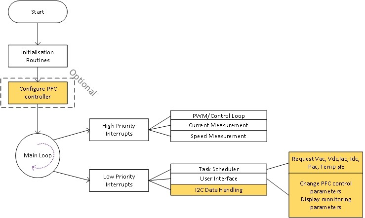
The PFC controller manages the boost PFC circuit’s control and monitoring. These tasks are offloaded from the main motor-control software workflow into low priority routines (Figure 6). The PFC controller parameters are configured during start-up, although this step can typically be skipped by writing the configuration parameters to the controller’s EEPROM, if such a feature is available. As shown in Figure 6, in a typical motor control system, the speed and current measurements and the PWM controller updates will be handled with high-priority interrupts in which the current measurement is synchronized with the PWM signal. The PFC controller can be set up to handle the input-side measurements such as input AC line voltage and current, DC bus voltage, input power, and PFC circuit temperature. These measurements aren’t critical to the motor-control algorithm, with the possible exception of the DC bus voltage measurement in a sensor-less algorithm. But they’re important to the overall system-level monitoring and controller optimization. They can thus be requested and handled within a low priority I2C data handling task or interrupt routine, and at a scheduling rate matched to the system monitoring time constant.
|
|
A Micrium Probe user interface for the platform is illustrated in Figure 7, in which the DC bus reference voltage has been set to 250 V. The monitoring of the AC and DC side variables in conjunction with the motor control is clearly seen.
|
|
The consequent saving in additional sensors, digital I/O, and analog pins on the processor, as well as the software overhead in scaling and interpretation of the measured variables, can potentially mean a reduction in processor cost, by being able to choose a lower performance variant, or a freeing up processor hardware and software footprint for other, higher priority or system-enhancing functions.
In this example, system startup sequencing with respect to AC line voltage, protection from DC bus undervoltage, overvoltage, and AC side overcurrent are all handled by the PFC controller. However, caution must be exercised in the overall system design in this regard, since the main control processor should always be made aware of control or protection actions being taken by the PFC controller, so that it doesn’t take independent action as a result of a secondary effect.
An example of this is where the PFC controller exercises a global disable on the PWM signals due to a transient overvoltage on the DC bus (due to a motor braking event, for example). If the controller isn’t aware of this, it’ll keep (unsuccessfully) attempting to adjust the PWM output to maintain its operating point. If the PFC controller re-enables PWM once the overvoltage transient disappears, the system may progress to a secondary fault due to a sudden, large increase in PWM duty cycle. Thus, care must be taken in managing communication of protection and sequencing between the PFC controller and motor control processor.


