
Contrasting sprites and GPUs and the HMI modeling approach
August 01, 2010

Model-based development provides the flexibility to create the graphical model once and then generate code for multiple graphical platforms.
Embedded developers creating new, small embedded displays have another option to consider beyond the Graphical Processing Unit (GPU). Sprite-based chips have found their place in automotive applications. These display controllers offer renderless manipulation of graphical images in a manner similar to a slide show. To assist engineers looking to solve this design dilemma, Altia offers a set of guidelines that can help them make an informed decision between these two options.
It is important to clarify that Altia has no obligation or agenda to support either mechanism. The company is not tied to any semiconductor companies or technologies, and its tools are not constrained to one operating system. These tools are proven with each solution, as companies are taking their Altia-generated graphics code to production on sprite-based chips and GPUs. Therefore, the goal of this discussion is to help designers get the best Human Machine Interface (HMI) running in their products on the best possible mechanism for their applications.
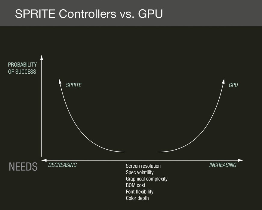
Let’s start with a diagram – a graphical contrast of sprites vs. GPUs in Figure 1 – and explore the details further.
|
|
Sprites: Simpler, but need planning
The sprite option is suitable for lower-end display products and is fast becoming an alternative to the GPU. So when does a sprite-based display controller successfully fit an HMI?
Sprites are a good solution when an HMI is composed of well-specified static images. The specification should be defined in advance so that designers know what is being implemented graphically in the HMI before development begins. There should not be a great deal of complexity with Z-ordering of visual and textual information. Sprite chips perform best on lower-resolution displays. These display controllers do not handle text as conveniently, often imposing restrictions like one character per sprite or a single color text per sprite. If a design is operating with a constrained Bill Of Materials (BOM), then sprite chips are a good option. They do not always require additional support chips like external RAM or flash and can operate with minimal use of internal resources.
This new hardware option does not come without challenges. At this point, sprite chips cannot easily support high-resolution displays or high color depth on lower-resolution displays. Memory bandwidth becomes a limiting factor with sprite chips as the sprite capability is integrated into the Display Controller Unit (DCU). The DCU constantly accesses graphical memory for all visible sprites every time a frame is clocked out to the display. Care must be taken to ensure the HMI does not violate bandwidth constraints by overlapping too many graphical objects, otherwise display failure will occur.
Layers of complexity
At present, if the HMI design is not known well enough at the beginning of the project, then sprite chips are a risky option. This is due to the high cost associated with changing the HMI graphical design once it is implemented on the chip. Sprite-based chips use the concept of a layer to represent an individual image (or sprite). Building any screen in the HMI requires placing all the images and text into these layers and positioning the layers as the designer wants them to appear on the display. The Z-order of graphics is determined by the Z-order of the layers. This is device-specific and typically cannot be changed after the layers are assigned. Therefore, Layer 1 will always appear on top of Layer 2, and so on. This is important only if the two layers intersect. The intersection is determined by the (x, y) position assigned to the layer and the pixel size of the sprite that the layer contains.
Getting the layout and organization of the layer content to appear as desired requires forethought. On parts with a limited number of layers, one can imagine the complexity that would go into defining the layer content and ordering so the images appear a certain way. Late change to layer arrangement could have a serious impact on the contents of all layers, even layers on unrelated screens. Therefore, success with sprite chips requires upfront design. Images and text must be carefully planned and arranged. If flexibility is needed with an HMI design, then rework time and cost become expensive.
It should be noted that although sprite chips are renderless, some rendering might be required to work within the constraints imposed by the chip. An example would be the number of sprites (layers) allowed by a sprite chip. A chip with a low total sprite count would be constrained when showing text where each text character occupies a single sprite. Such a chip would require that individual text characters be combined or rendered into a single memory block, which could be shown as a single sprite. The render operations can be accomplished using hardware resources like a DMA engine if allowed by the device.
GPUs: Flexible and robust, but more complex
The alternative to the sprite chip is the GPU, a proven solution with a wide range of samples running in production. This mature and well-supported technology offers tremendous flexibility during development.
The GPU presents important benefits that make it an obvious selection for specific applications. Unlike with sprite chips, memory bandwidth limitations will not result in display failure since the GPU is separate from the DCU. This allows higher-display resolutions and color depths than with sprite chips. There are very few restrictions regarding layer composition and blending. Designers can be much more flexible with text and can render more sophisticated animations on a GPU. This is a great solution to consider when the HMI specification is volatile. A GPU has fewer layers, thus reducing complexity when structuring an HMI.
More resources around the engine
The GPU requires some flexibility with a BOM, as this solution is perceivably more expensive than a sprite, especially when considering the additional external RAM and flash that it may require. GPUs are generally coupled on a System-on-Chip (SoC) with a far more powerful host processor than typically found with a sprite-based display solution. When opting for a separate GPU and host processor, increased complexity is introduced in the board layout.
The GPU presents a unique set of challenges. First, total cost is a definite consideration, especially when counting multiple chips, board real estate, and PCB layout complexity. As GPUs can support deeper color depths with greater text and font control image, memory consumption has a tendency to explode. Once the amount of image memory gets too big, image compression starts to become a constraint. Designers need to deal with image compression, decompression, and the associated costs and performance issues, which means more complexity and trade-offs. Finally, variability in GPU programming remains an issue.
Despite discussion about “the open” – OpenGL and OpenVG – the standards are not implemented the same way throughout the industry. Drivers vary greatly, and different semiconductor companies optimize differently. So getting optimized performance for a specific platform still requires some amount of customization.
Modeling and generating code pays off
Considering the trade-offs in the underlying graphics engine and the task of programming at hand, the question remains: How do designers get a winning HMI design? Model-based development is the path to the most efficient and effective HMI.
Where does model-based development factor into the everyday engineering effort? A traditional development process consists of time spent defining natural language requirements, followed by painful and expensive manual translation steps to create a software design and implementation from this natural language requirement. When a model-based engineering environment is introduced, the requirements process is more efficient because executable models of the intricate HMI behavior are created. An overview of a model-based environment is shown in Figure 2.
|
|

A model that can represent HMI behaviors can not only be done more quickly than writing a natural language document, but it can also depict graphical behavior that is nearly impossible to effectively define in a text-based document. These executable specifications can be baselined as a requirement model and then act as the initial software design, which is then refined for embedded target performance and limitations. Then, with products like Altia DeepScreen, an embedded implementation can be autogenerated from this refined executable model. Designers refine the model built as a requirement and then autogenerate the embeddable code for it, considerably reducing the development effort.
Model-based development, especially when paired with a graphics code generator, offers the flexibility to create the graphical model once and then generate code for multiple graphical platforms. This allows designers to try it on a variety of platforms until the right fit for the application is found. When the time comes to select hardware, be it a sprite or GPU, model-based development provides a sure-fire method for achieving a winning combination of hardware and HMI.
|
|

Altia 719-598-4299 [email protected] www.altia.com


