
Building embedded software with the Eclipse Process Framework
July 01, 2006
Story
Besides the typical work flow used for developing embedded software products, such as requirements gathering, analysis, system design, detailed design, testing, and project management, there is one additional challenge in the medical device industry – compliance.
The challenge:
Besides the typical work flow used for developing embedded software products, such as requirements gathering, analysis, system design, detailed design, testing, and project management, there is one additional challenge in the medical device industry – compliance. Products developed for the U.S. market are regulated by the Food and Drug Administration (FDA) through Quality Systems Regulations (QSR) 21 CFR Part §820.30, which essentially require[1]:
- Proper documentation to be maintained in a Design History File (DHF)
- 21 CFR Part 11 also governs the usage of electronic signatures in DHF to facilitate electronic documentation in lieu of paper version
- International markets to be ISO 13485:2003 compliant and meet the EU MDD 93/42 regulations
- Compliance with Current Good Manufacturing Practices (CGMP) and Good Design Practices (GDP), both also dictated by the FDA
Traditional approaches
In order to meet compliance goals, medical device development teams start a DHF at the inception of a project. The contents of this file may include informal, handwritten requirements and design notes, as well as formal architecture and design documents in the form of printouts and source code excerpts. For many development teams that are source code centric, the DHF may include requirements documents, ad hoc formal design documents, and a large number of source code listings, reflecting how the expressed requirements are being implemented faithfully as source code[2]. QSR requires this work flow, mandating that traceability must be established between requirements and their exact implementation to prove that the device is being used for its intended purpose; however, the method of establishing traceability is not spelled out. Source code is typically submitted since it is readily available, and most teams also use source code as the medium for representing system architecture and design. This is pretty typical in the absence of a formal modeling approach integrated into the development process[3].
Design input and output
Figure 1 shows a recommended development process from the FDA Design Control Guide[4]. Note the fact that QSR compliance can be achieved in conjunction with GDP by adhering to the iterative development steps shown. Much of system verification is performed against the requirements by measuring design output against design input[5]. Design inputs are a set of specifications derived initially from the user requirements with the goal that intended use of the device should be spelled out as a set of requirements. Design output, in turn, is a set of procedures defined by the device maker ensuring that the completed work tallies with the corresponding design input. This essentially mandates a need for traceability between these two milestones.
|
|
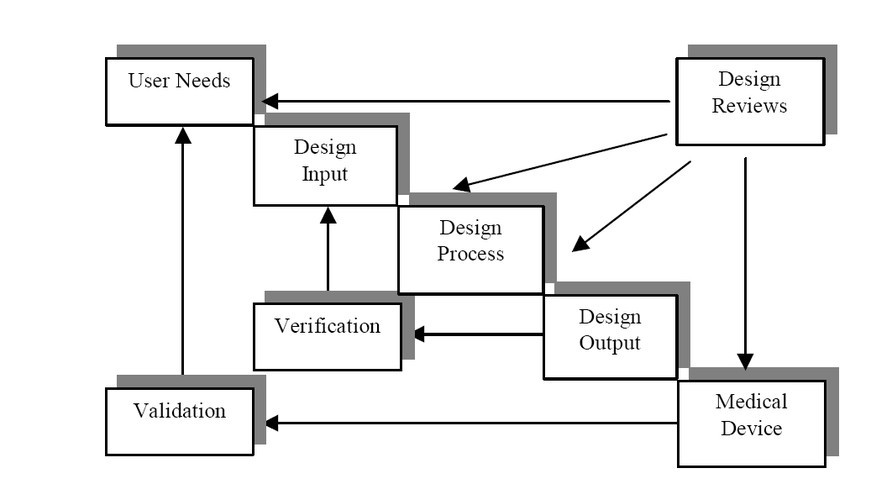
Traditionally, development processes include as design input a formal or semiformal set of word processor documents and a few models reflecting a set of specifications against which the system is to be built. This input is transformed into the predisclosed set of deliverables mentioned in the design output. Therefore, design output may include, in the case of system software, a listing of the source code belonging to the application. The goal is to disclose the intended use of the device and ensure that specifications have been implemented and design goals met.
Verifying the design
Design input and output milestones are integral parts of a medical device development process and are applied to a large number of devices; therefore, they do not specify what methods should be used for the verification shown in the process outlined in Figure 1. Device makers use an array of tools and processes for this purpose, but most rely on textual requirements documents and source code listings as described for design input and output. Figure 1 includes a design verification step where the design output is verified against the design input.
Validating the system
Since most teams consider source code as the ultimate measure of a system’s implementation, running the completed source code on the actual device frequently demonstrates the intended purpose of the device. This is a source-centric approach, as validation occurs by executing the application code compiled for the real device.
While effective, traditional methods of validating the system prove to be costly and error prone. The task of unit testing the evolving system on the target device may be cumbersome and slow. It may not be possible to put the machine through all the intended usage scenarios without incurring a heavy expense or logistical obstacles, such as incomplete or nonexistent hardware, which may hamper the final testing on the device. An incomplete platform may render wrong results for the tested application.
As software and system bugs are found during unit testing and are corrected, their associated design and requirements may need updating to reflect the changed source code. Depending on the size of the application, this may become time consuming and susceptible to errors as some changes may be missed, causing a mismatch between the DHF and the actual implemented system.
A new approach using automated tools
Design controls and QSR don’t require the actual operational medical device as the basis for system verification and validation. As far as the FDA is concerned, it is sufficient to simply demonstrate the collected data as proof of intended use of the device. This data can be collected from the actual device as well as a simulated execution of the device, where automated application development tools offer unparalleled efficiency gains. Figure 2 presents a process centered on validation and verification. Like the FDA process described earlier, this process hinges on iterative development of design output based on design input. Figure 2 also traces requirements to system validation, while architecture and design activities are traced to system verification. All the steps shown are performed automatically through the requirements traceability and the executable model features provided by the modeling tools[1].
|
|

An example of automated validation and verification
In a model-driven process, both architecture and design of the application are carried out in the modeling tool[3]. Additionally, design tools can automatically generate unit test cases from design models, as shown in Figure 3. Here, models for both the design and the test case are executable. The first goal is to verify the underlying design, then to test the design, depicting the actual usage scenarios for the device. Most defects and design oversights are caught during this model verification phase. Unit testing can put the design through any possible scenario, many of which may be difficult to create on the actual device. In the forthcoming example, tests can show the system’s behavior in the unlikely event that the patient exhibits no detectable pulse in the middle of monitoring his or her blood oxygen levels. Creating this test case on the real device will require stopping a subject’s heart, to which they may object.
|
|

Defects and oversights detected are immediately corrected in the design, thus eliminating the need for manually changing the code and the design documentation. This contrasts traditional development, in which defects are fixed inside the source code after executing it on the real device. This happens later in the development process, and system debugging therefore is much slower than a model-driven approach.
The example in Figure 4 illustrates a design for a blood oxygen monitor used to measure blood oxygen levels as well as pulse rate through a finger clip sensor. The design shows a state machine responsible for de-packetizing the sensor data containing blood oxygen levels (SpO2) and pulse rate. By injecting either real or simulated sensor data, the state machine shown in the diagram can quickly verify correct operation. Furthermore, the test case in Figure 4 verifies that both pulse rate and oxygen levels are within a safe range. This test case is run alongside design verifications to ensure patient safety during unforeseen or complex events that are difficult to create.
|
|

Additionally, an automated requirements management tool can be used so that traceability can be established between the design components, such as the state machine pictured in Figure 4, and the requirements.
Finally, for system validation, test cases are traced to the system’s operational requirements. This is automated through requirements traceability feature between a formal requirements management tool and the modeling environment. In other words, a fully automated validation and verification process can be established.
Development tools
Telelogic provides life-cycle development tools (shown in Figure 3) that cover the whole arena of system validation and verification as required by QSR. DOORS requirement management tool is used as the basis for creating the design input, and both system requirements and validation tests are managed inside DOORS as structured and traceable sets of objects.
Two different tools provide a modeling solution depending on the nature of the medical device being developed. For conventional, standalone medical devices that typically use a single board embedded computer and a Real-Time Operating System (RTOS), Telelogic’s Rhapsody provides system architecture and design support as well as automatic source code generation. Rhapsody is capable of supporting out-of-the-box, major RTOS platforms. It also provides the added capability of target-hosted cosimulation, which proves valuable during the validation and verification process when target-level verification becomes necessary.
Telelogic TAU can be used for complex medical devices using multiple platforms, or an arbitrary combination of embedded and desktop systems. This may include devices such as Computed Tomography (CT) scanners or other systems that carry an array of interrelated platforms, including headless desktop computers and monitoring workstations running conventional operating systems such as Linux, UNIX, or Windows. TAU supports language and operating system independent modeling, and can deploy the same models on any arbitrary platform using a mix of programming languages. This is described as Platform Independent Modeling (PIM), where a single set of models can be used on many different or undefined platforms. The concept of PIM, therefore, adds another dimension to increased productivity, allowing designed components to be used in future generations of unknown platforms.
The resulting documentation from the automated development process provides an integrated paper trail originating both from requirements management and modeling activities. This paper trail is automatically created by Telelogic’s DocExpress, which has visibility into all Telelogic tools used in this example. DocExpress automatically creates word processor pages incorporating text and diagrams from the tools used, and is fully configurable by the user.
A better, cheaper development process
When designing medical devices, design guidelines and regulations as dictated by the FDA QSR can be addressed concurrently with best practices in system and software development. This not only decreases development costs, but also facilitates the validation and verification process dictated by QSR, resulting in a more reliable medical device with less chance of failure in the field. Additionally, this provides live content for the DHF, which is automatically managed and produced. The set of life-cycle management solutions from Telelogic aims to automate the development process through the use of requirements management, system and software modeling, and automated, model-based testing tools, including DOORS, Rhapsody, TAU, and DocExpress.
References
[3] Badr, I., “Rapid Development through Agile Modeling,” Telelogic white paper, February 2005
Irv Badr, currently a senior product marketing manager for Telelogic, has nearly 20 years of development experience in embedded and modeling industries, designing communication infrastructure for medical devices, networking nodes, digital cable transmission, and industrial controls. He also served as technical lead for sales and marketing of RTOSs, and for modeling tools with TimeSys Corp. and Artisan Software. Irv has a BS in Biomedical Engineering from the University of Illinois and a technical MBA from Northwestern University.
To learn more, contact Irv at:
Telelogic
9401 Jeronimo Road
Irvine, CA 92618
Tel: 949-830-8022
Fax: 949-830-8023
E-mail: [email protected]
Website: www.telelogic.com


