
Using a memory protection unit with an RTOS
May 08, 2018
Story

Memory-protection units (MPUs) have been available for years on processors such as the Cortex-M, and yet, embedded developers shy away from using them. Is it because they aren?t useful?
This article is the first in a series. The other three parts can be found here: Part 2, Part 3, and Part 4.
Memory-protection units (MPUs) have been available for years on processors such as the Cortex-M, and yet, embedded developers shy away from using them. Is it because they aren’t useful? Is it because MPUs are complex devices? Do they add too much overhead? In this article, and the subsequent multi-part series, these questions and more will be answered.
In Part 1, I’ll cover MPU basics using generic concepts. Then, I’ll get into specifics using the MPU found in an ARM Cortex-M. Finally, I’ll show you how to organize your code by processes, how a process can communicate with one another, what happens when a process accesses memory or I/O outside of its assigned memory, and finally, offer some recommendations when using an MPU.
I’ll start off with a brief description of what an RTOS is and then show how an MPU fits into the picture. An RTOS (a.k.a., real-time kernel) is software that manages the time of a central processing unit (CPU) or a microprocessing unit (MPU) as efficiently as possible. Most RTOSs are written in C and require a small portion of code written in assembly language to adapt the RTOS to different CPU architectures.
When you design an application (your code) with an RTOS, you simply split the work into tasks, each responsible for a portion of the job. A task (also called a thread) is a simple program that thinks it has the CPU all to itself. Only one task can execute at any given time on a single CPU. Your application code also needs to assign a priority to each task based on the task importance and a stack (RAM) for each task. In fact, adding low-priority tasks will generally not affect a system’s responsiveness to higher-priority tasks. A task is also typically implemented as an infinite loop. The RTOS is responsible for the management of tasks. This is called multitasking.
Multitasking
Multitasking is the process of scheduling and switching the CPU between several sequential tasks. It provides the illusion of having multiple CPUs and maximizes the use of the CPU, as shown in Figure 1. Multitasking also helps in the creation of modular applications. With an RTOS, application programs are easier to design and maintain.
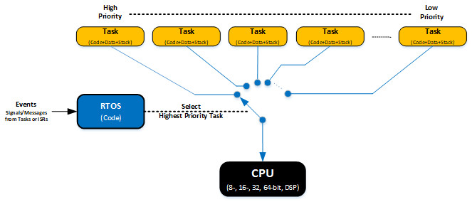
[Figure 1 | The RTOS decides which task the CPU will execute based on events.]
Most commercial RTOSs are preemptive, which means that the RTOS always runs the most important task that is ready-to-run. Preemptive RTOSs are also event driven, which means that tasks are designed to wait for events to occur to execute. For example, a task can wait for a packet to be received on an Ethernet controller; another task can wait for a timer to expire, and yet another can wait for a character to be received on a UART. When the event occurs, the task executes and performs its function, if it becomes the highest priority task. If the event that the task is waiting for does not occur, the RTOS runs other tasks.
Waiting tasks consume zero CPU time. Signaling and waiting for events is accomplished through RTOS API calls. RTOSs allow you to avoid polling loops, which would be a poor use of the CPU’s time. The example below shows how a typical task is implemented:
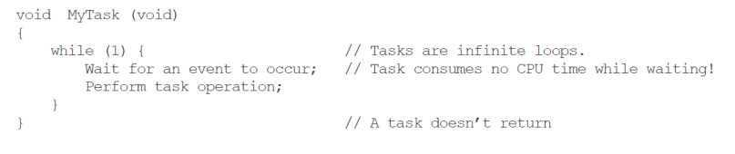
The event that the task waits for can be triggered either from a task or a peripheral device interrupt handler through an RTOS API call. The API would typically run the RTOS scheduler, which would then decide to either switch to a new, more important task or simply resume the interrupted task (if the event was from an interrupt).
An RTOS provides many useful services to a programmer, such as multitasking, interrupt management, inter-task communication and signaling, resource management, time management, memory partition management and more.
An RTOS can be used in simple applications where there are only a handful of tasks, but it’is a must-have tool in applications that require complex and time-consuming communication stacks, such as TCP/IP, USB (host and/or device), CAN, Bluetooth, Zigbee, and more. An RTOS is also highly recommended whenever an application needs a file system to store and retrieve data as well as when a product is equipped with some sort of graphical display (black and white, grayscale, or color). Finally, an RTOS provides an application with valuable services that make designing a system easier.
For performance reasons, most RTOSs are designed to run application code in privileged (or supervisor) mode, thus allowing those applications full control of the CPU and its resources. This is illustrated in Figure 2, where all tasks and ISRs have unrestricted access to memory and peripherals. Unfortunately, this implies that application code can corrupt the stacks or variables of other tasks either accidentally or purposely. In addition, allowing any task or ISR full access to all peripherals can have dire consequences.
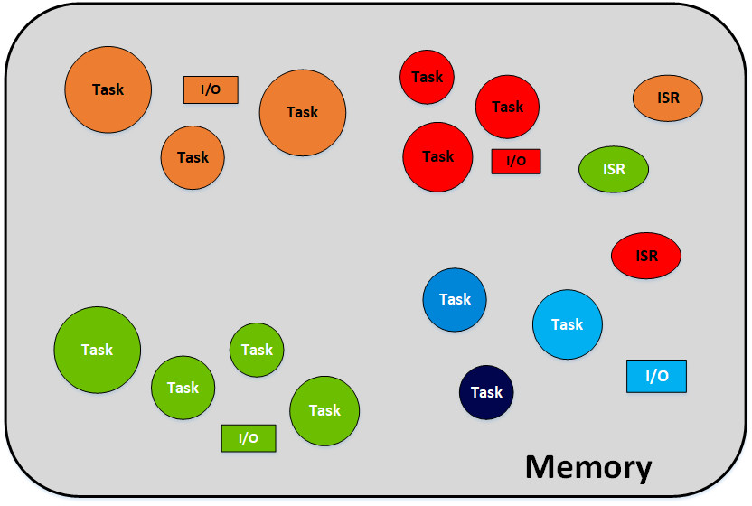
[Figure 2 | Shown is an RTOS and application code running with full privileges.]
What is an MPU?
An MPU is hardware that limits access to memory and peripheral devices to only the code that needs to access those resources. It enhances both the stability and safety of embedded applications and is thus often used in safety-critical applications such as medical devices, avionics, industrial control, and nuclear power plants.
MPUs are now finding their place in the IoT because limiting access to memory and peripherals can also improve product security. Specifically, crypto keys can be hidden from application code preventing access from an attacker. Isolating the flash memory controller with the MPU can also prevent an attacker from changing an application, thus only allowing trusted code to perform code updates.
With the help of an MPU, RTOS tasks are grouped into processes, as shown in Figure 3. Each process can consist of any number of tasks. Tasks within a process are allowed to access memory and peripherals that are allocated to that process. However, as far a task is concerned, it doesn’t know that it’s part of the same process except for the fact that it’s given access to the same memory and I/Os as the other tasks within the process. When you add an MPU, very little has to change from a task’s perspective since your tasks should be designed such that they don’t interfere with each other unless they have to anyway.
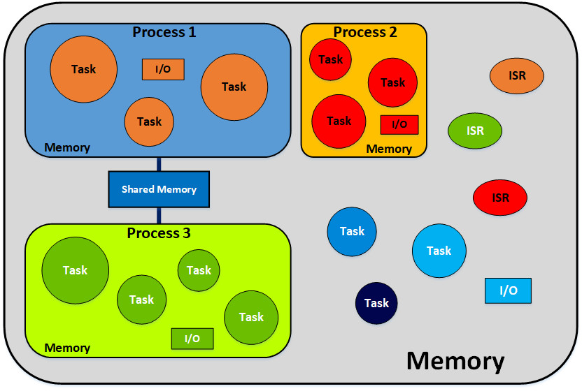
[Figure 3 | Separating an application into multiple processes.]
Figure 3 shows that processes can communicate with one another through shared memory. In this case, the same region(s) would appear in the MPU table for both processes. An application can also contain system level tasks as well as ISRs that have full privileges, thus allowing them access to any memory location, peripheral devices, and the CPU itself. If a task attempts to access a memory location or a peripheral outside of its sandbox, then a CPU exception is triggered, and the exception handler can terminate the task or all tasks belonging to the process.
Exactly what happens when such a violation occurs greatly depends on the application and to a certain extent which task causes the violation. For example, if the violation is caused by a graphical user interface (GUI), then terminating and restarting the GUI might be acceptable and might not affect the rest of the system. However, if the offending task is controlling an actuator, the exception handler might need to immediately stop the actuator before restarting the task. Ideally, access violations are caught and corrected during product development because, otherwise, the system designer will need to assess all possible outcomes and make decisions on what to do when this happens in the field. Recovering from an MPU violation can get quite complicated.
In RTOS-based applications, each task requires its own stack. Stack overflows are one of the most common issues facing developers of RTOS-based systems. Without hardware assistance, stack overflow detection is done by software and unfortunately rarely caught in time, which potentially makes the product unstable, at best. The MPU can help to protect against stack overflows, but unfortunately, it’s not ideal.
The addressable addresses of a process is defined by a table that’s loaded into the MPU when the RTOS switches-in a task. The table simply defines the memory (or I/O) ranges (called regions) that a task is allowed to access as well as attributes associated with those regions. Attributes for a region may specify if a task is allowed to read/write from/to a region, or only be allowed to read, or execute code from the region (eXecute Never attribute, i.e. XN), etc. The eXecute Never attribute is highly useful as it can be used to prevent code from executing out of RAM, thus reducing the ability for hackers to perform code injection attacks. The number of entries in the table depends on the MPU.
As shown in Figure 4, an MPU region can be used to detect stack overflows. In this case, a small region is used to overlay the bottom of each task stack. The MPU attributes are configured such that if any code attempts to write to that region, the MPU generates an exception. The size of the region determines how effective this technique would be at catching a stack overflow. The larger the region, the more chances you’d catch a stack overflow, but at the same time, the more RAM would be unavailable for your stack. In other words, the RedZone in the figure would be considered unusable memory because it’s used to detect illegal writes. A good starting point for the RedZone size would be 32 bytes. If your task stack is 512 bytes, then 32 bytes would only represent about 6%, leaving 480 bytes of usable stack space.
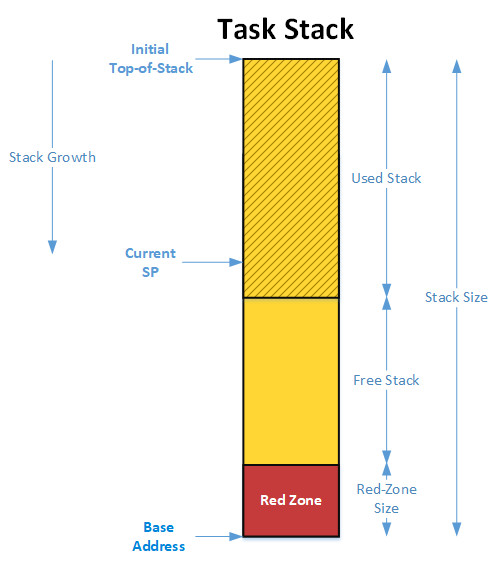
[Figure 4 | Pictured is the MPU region used to detect stack overflows.]
Because of the fairly limited number of regions available in an MPU, regions are generally set up to prevent access to data (in RAM) and not so much to prevent access to code (in flash). However, if your application doesn’t make use of all the regions, security would also be improved by limiting access to code.
The process table is typically assigned to a task when the task is created. The RTOS simply keeps a pointer to this table in the task’s control block (TCB). An RTOS context switch now includes additional code to update the MPU with the process table of the task being switched in, as shown in Figure 5. Notice that the MPU configuration doesn’t need to be saved when a task is switched out since the configuration for the task is always loaded from the table.
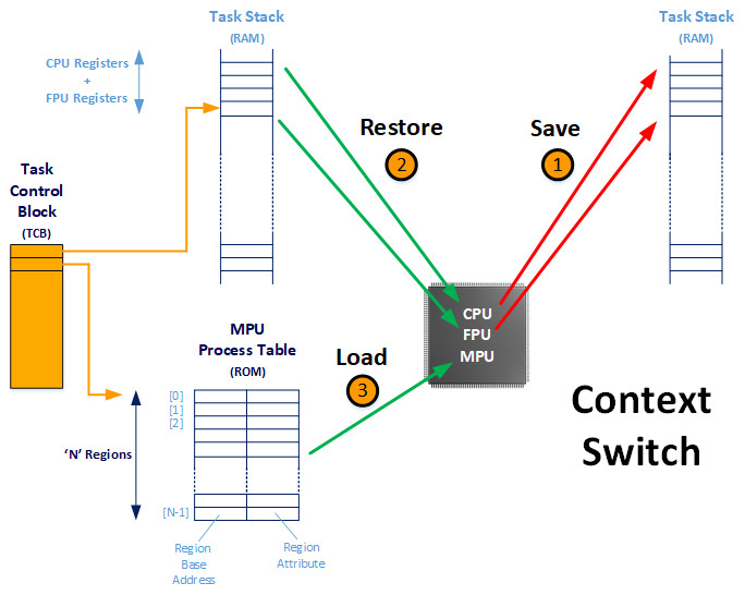
[Figure 5 | The MPU configuration is updated on a context switch.]
In summary, an MPU is hardware that limits the access to memory and peripheral devices to only the code that needs to access those resources. Tasks are grouped into processes that are isolated from one another. If a task attempts to access a memory location or a peripheral device outside of its allotted space, then a CPU exception is triggered, and depending on the application, the offending task or the whole process can be terminated. The MPU can be used to detect stack overflows, but each task needs to give up a small portion of its stack to be used as a RedZone.
Each process is defined by a process table. A pointer to the process table is saved in the task’s TCB when the task is created. This allows the RTOS to load the MPU with the task’s process table when the task is switched-in. This operation obviously consumes extra CPU clock cycles, which adds to the context switch time. Generically speaking, extending an RTOS to use an MPU seems to be quite straightforward; however, in practice, there are quite a few issues to consider as we’ll see in Part 2.
References
- Jean J. Labrosse, Detecting Stack Overflows (Part 1 of 2), March 8, 2016
- Jean J. Labrosse, Detecting Stack Overflows (Part 2 of 2), March 14, 2016


