
Powering single-board computer and computer-on-module systems
June 14, 2018
Story

Single-board computers and computer-on-module systems embed all of the functions of a computer onto a single circuit board, and are commonly used in industrial applications.
Single-board computers (SBCs) and computer-on-module (CoM) systems embed all of the functions of a computer onto a single circuit board, and are commonly used in industrial applications in a rackmount format for factory automation and process control.
The heart of the SBC is the core processor, and newer processors have special power requirements. More recent processors include the AM57xx series Sitara processor family from Texas Instruments (TI), which are single or multicore Arm Cortex-A15 processors with an integrated digital signal processor (DSP) and industrial communication subsystem (ICSS). The latest 64-bit processor from Intel is the Ice Lake U/Y, but there are many other x86 processor options to choose from.
SBCs are embedded in other devices to provide interfacing and control in a wide range of applications, from slot machines to factory automation programmable logic controllers (PLCs) requiring a high level of flexibility, since the environment where the SBC is placed can vary. In some end applications, airflow is not available, and a high thermally efficient solution is necessary.
SBCs come in various sizes and have a dedicated form factor requiring a high level of integration. This requirement drives reduced external components for a smaller, lighter and more reliable product in the power-supply section. Discrete step-down converters with integrated field-effect transistors (FETs) offer a high level of design flexibility and thermal performance.
Point-of-load architecture considerations
SBCs benefit from a DC/DC point-of-load power solution that supports the needs of advanced processors, offers high efficiency with good thermal performance, and reduces the overall component count and total cost. SBCs are usually provided 5V or 12V from an external power source, but some applications have only 24V available to provide. Since newer processors have much lower core voltages, duty-cycle limitations make it difficult to regulate a sub-1V core rail with a 24V input while switching at a higher frequency (such as 1MHz or above) in order to maintain a small form factor.
As shown in the equation below, for example, to regulate 1V from a 24V input (with a 4.2% duty cycle), the minimum controllable on-time must be lower than 40ns when switching at 1MHz to avoid pulse skipping. Implementing an intermediate bus voltage which converts 24V to either 5V or 12V solves the pulse skipping problem and is more suitable for powering low voltage processors.
Operating voltage accuracy
As the process technology advances, the processors require tighter voltage accuracy and lower operating voltages. The processor data sheet may specify the voltage tolerance as a percentage or value in millivolts, which includes DC, AC and ripple variations over the entire operating temperature range. Any voltage outside this range is not recommended, and the processor can behave unexpectedly.
You must also consider the tolerance of the resistor divider used by the DC/DC converter; the routing and trace losses of the circuit board; and the variations of the application, like input voltage variations, temperature swings and fast changes in the load. All of these factors contribute to DC/DC converter accuracy. Many designers will want headroom or margin to make sure that the solution is always within the tolerance expectation of the processor.
It is important to check the feedback voltage accuracy of the DC/DC converter in the data sheet rather than the front page. Table 1 shows the regulated feedback voltage specification of the TPS54424, which is a 4.5V to 17V 4A converter with a reference accuracy that is ±50mV or ±0.83% over input voltage and temperature variations. Choosing tighter tolerance resistors improves the total output voltage accuracy. If you need more headroom, you can choose 0.1% or 0.5% resistors [1], even though they may cost a little bit more. The additional headroom will allow you to meet the total ±3% or ±5% output voltage variation with less bulk and bypass capacitance.
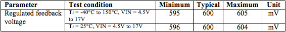
[Table 1 | Feedback voltage regulation as shown in the TPS54424 data sheet]
It is always wise to place the DC/DC converter as close to the load as possible, although layout constraints, connectors and board density requirements can interfere. A DC/DC converter’s remote sense feature will compensate for any voltage drops from long trace lines. This feature is especially useful when routing higher currents when the voltage drop can be a large portion of the overall DC error.
Since the load profile can change dramatically in SBC applications, it is important to consider AC transient performance. Choosing a DC/DC converter with a nonlinear control mode, such as constant on-time control , TI’s D-CAP3 control mode or DCS-Control, allows a fast transient response time with reduced output capacitance. A nonlinear control mode improves AC transient performance compared to a linear control mode. [2].
It’s possible to tune DC/DC converters with externally compensated current-mode control for a fast transient response as well, and synchronize them to an external clock. Figure 1 shows the TPS568215 8A step-down converter achieving a ±30mV total voltage deviation from a 12V input to 1.2V output at 1.2MHz, with less than 200µF of ceramic output capacitance using D-CAP3 control mode.

[Figure 1 | TPS568215 transient response]
Sequencing
The processor manufacturer may recommend power sequencing to eliminate bus contention issues between the various blocks of the processor and other processors on the board, to reduce power-up/power-down stresses on the processor’s internal isolation structures, or to stagger supplies to avoid startup in-rush currents. There are several methods to power up and down a number of supplies, but the most popular method is sequential sequencing.
Sequential sequencing connects the power good (PG) pin of one voltage regulator to the enable (EN) pin of another voltage regulator. Figure 2 shows the power-up configuration for two converters, and you can add more rails onto the series, which enables you to stagger the voltage rails and avoid high in-rush currents during startup.
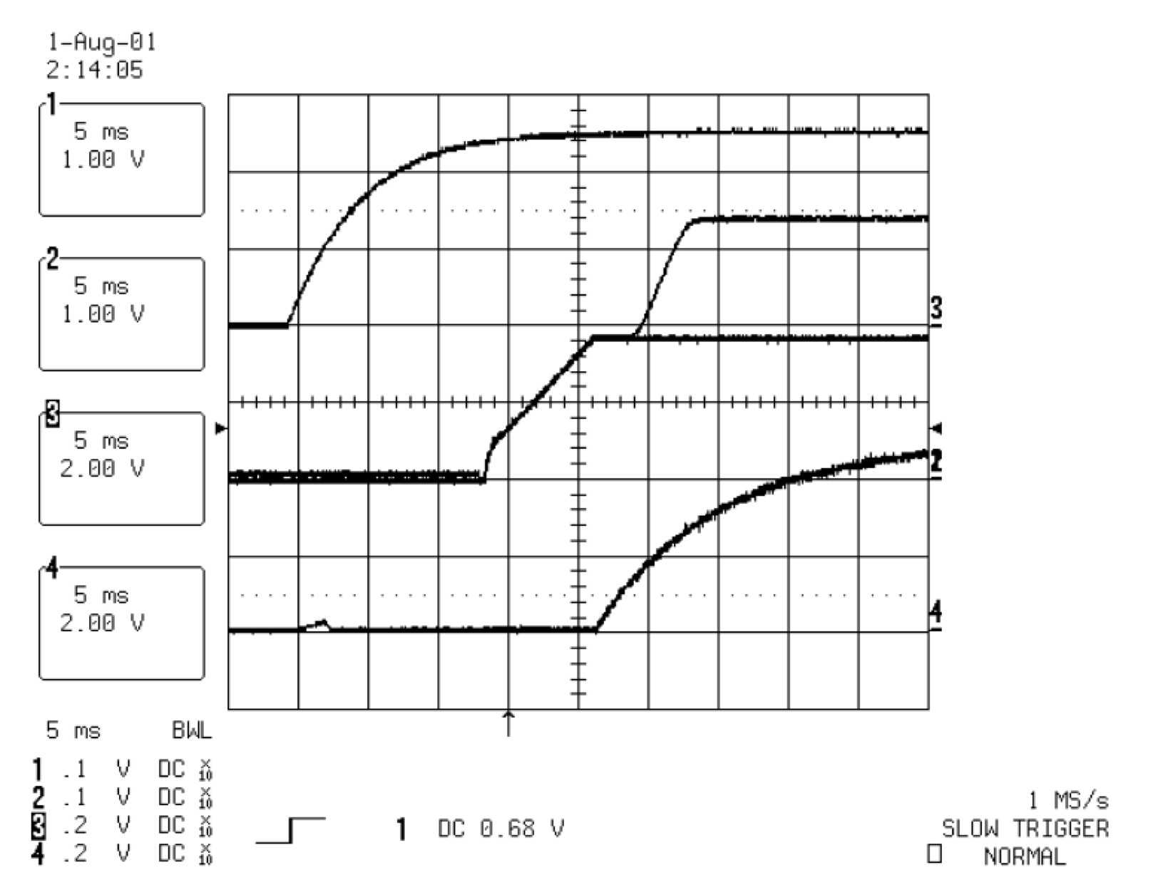
[Figure 2 | Output voltage waveform for sequential startup: channel 1: 3.3V; channel 2: Vcore; channel 3: PG; channel 4: input voltage]
A DC/DC converter with a tracking pin, such as the TPS62135 (4A output current) shown in Figure 3 or TPS62148 (2A output current), helps with power-supply sequencing and performs a more reliable power-down function than with the PG and EN pins. Power-supply sequencers are also available that very reliably control multiple rails, but consume more board space [3].
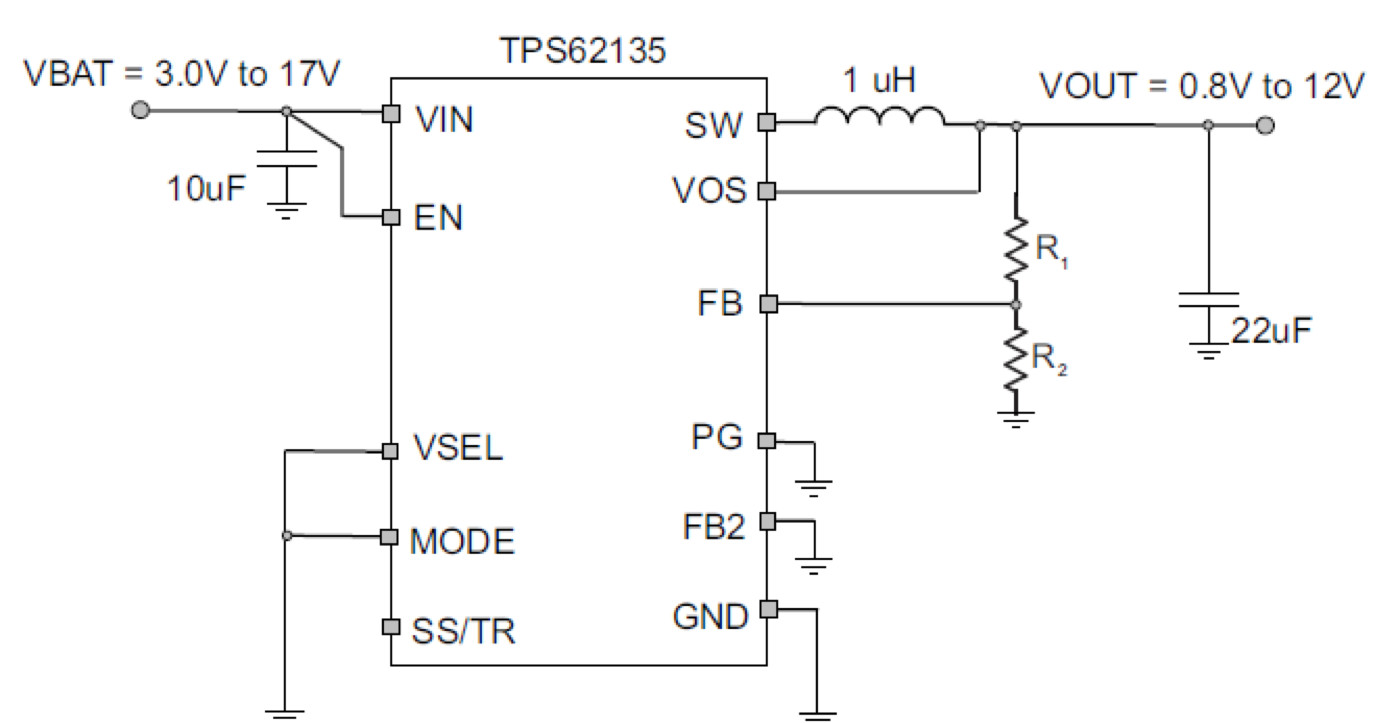
[Figure 3 | TPS62135 with track, PG and EN pins for sequencing]
Thermal performance
SBCs are typically built on a circuit board with four, eight or even 16 layers, depending on the form-factor constraints. Since the SBC is designed for use in a wide variety of applications, you must pay special attention to DC/DC converter selection to ensure that the SBC operates in thermally challenging environments with or without available airflow. Higher circuit board temperatures translate to lower reliability, and higher current DC/DC converters contribute significantly to the overall thermal budget.
As shown in the safe operating curve of Figure 4 and the efficiency plot in Figure 5, the high-efficiency TPS543B20 25A DC/DC converter delivers 25A and 1V with an ambient temperature of 90°C, without airflow. At 10A and 1V, the entire solution will dissipate only 1W.
Derating the DC/DC converter is good design practice when optimizing for efficiency and size. In some cases, DC/DC converters are available in pin-compatible output current options or offered with a programmable current limit to provide flexibility.
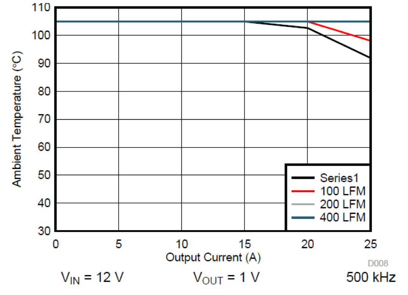
[Figure 4 | TPS543B20 safe operating area]
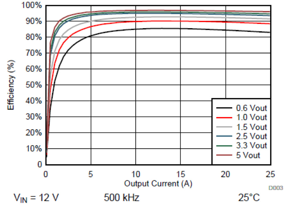
[Figure 5 | TPS543B20 efficiency plot]
Power modules
Power modules are quickly gaining in popularity because of their high integration, which enables faster design time, ease of use and a smaller printed circuit board (PCB). These characteristics are important in SBC and CoM systems due to the increasing number of power-supply rails, while available board space is very limited.
A common challenge with power modules or any other device that must provide the same functionality in a smaller space is thermal performance. TI’s TPS82130 is a MicroSiP power module that accepts up to a 17V input voltage and delivers up to 3A of output current in a tiny 2.8mm-by-3mm package that is only 1.5mm tall. It has an exposed thermal pad on its bottom side to improve thermal performance. Since this thermal pad connects to ground potential, using vias to internal ground layers in the PCB removes heat and decreases the power-module temperature [4].
Conclusion
Products using SBCs and CoMs benefit from a high performance and high efficient point-of-load power solution. DC/DC converters designed to power advanced processors will solve the voltage accuracy, load transient, and power sequencing challenges. Since SBC and CoM may be use in space-constrained environments with little or no airflow, small and efficient DC/DC converters are required to solve difficult thermal challenges.
Additional resources
- Watch the video, “How to meet FPGA’s DC voltage accuracy and AC load transient specification”
- Check out the webinar, “DC/DC Buck Converters: What do all of these features mean?”
- Learn more about power management for FPGAs and processors.
- Download the Small Efficient Flexible Power Supply Reference Design for NXP iMX7 Series Application Processors.
- Read the blog post, “Look at the details when designing an industrial PC – 1% is not always 1%.”
References
- Kollman, Robert. “Power Tip #18: Your regulator’s output-voltage accuracy may not be as bad as you think,” EETimes, August 4, 2010.
- Texas Instruments Control Mode Quick Reference Guide, SLYT710, 2018.
- TI power sequencers.
- Horton, Sandra, and Chris Glaser, “Improving the thermal performance of a MicroSiP power module,” Analog Applications Journal SLYT724, 3Q 2017.
- TI single board computers.
- TI AM437x Discrete Power Reference Design.


