How to choose cool running, high power, scalable POL regulators and save board space
August 13, 2018
Blog
IC designers often avoid dealing with the dreaded topic of heat ? a job that usually falls to the package engineer.
The art of designing efficient and compact DC-to-DC converters is practiced by a select group of engineers with a deep understanding of the physics and supporting mathematics involved in conversion design, combined with a healthy dose of bench experience. A deep understanding of Bode plots, Maxwell’s equations, and concerns for poles and zeros figure into elegant DC-to-DC converter design. Nevertheless, IC designers often avoid dealing with the dreaded topic of heat — a job that usually falls to the package engineer.
Heat is a significant concern for point-of-load (POL) converters where space is tight among delicate ICs. A POL regulator generates heat because no voltage conversion is 100% efficient (yet). How hot does the package become due to its construction, layout, and thermal impedance? Thermal impedance of the package not only raises temperature of the POL regulator, it also increases the temperature of the PCB and surrounding components, contributing to the complexity, size, and cost of the system’s heat removal arrangements.
Heat mitigation for a DC-to-DC converter package on a PCB is achieved through two major strategies:
Distribute it through the PCB
If the converter IC is surface-mountable, the heat conductive copper vias and layers in the PCB disperse the heat from the bottom of the package. If the thermal impedance of the package to the PCB is low enough, this is sufficient.
Add airflow
Cool airflow removes heat from the package (or more precisely, the heat is transferred to the cooler fast air molecules in contact with the surface of the package).
Of course, there are methods of passive and active heat sinking, which, for simplicity of this discussion, are considered subsets of the second category.
When faced with rising component temperatures, the PCB designer can reach into the standard heat mitigation toolbox for commonly used tools such as additional copper, heat sinks, or bigger and faster fans, or simply more space — use more PCB real estate, increase the distance between components on the PCB, or thicken the PCB layers.
Any of these tools can be used on the PCB to maintain the system within safe temperature limits, but applying these remedies can diminish the end product’s competitive edge in the market. The product, say a router, might require a larger case to accommodate necessary component separation on the PCB, or it may become relatively noisy as faster fans are added to increase airflow. This can render the end product inferior in a market where companies compete on the merits of compactness, computational power, data rates, efficiency, and cost.
Successful thermal management around high power POL regulators requires choosing the right regulator, which demands careful research. This article shows how a regulator choice can simplify the board designer’s job.
Don’t judge POL regulators by power density alone
A number of market factors drive the need to improve thermal performance in electronic equipment. Most obvious, performance continuously improves even as products shrink in size. For instance, 28 nm to 20 nm and sub-20 nm digital devices burn power to deliver performance, as innovative equipment designers use these smaller processes for faster, tinier, quieter, and more efficient devices. The obvious conclusion from this trend is that POL regulators must increase in power density: (power)/(volume) or (power)/(area).
It is no surprise that power density is often cited in regulator literature as the headline specification. Impressive power densities make a regulator stand out, giving designers quotable specifications when choosing from the vast array of available regulators. A 40 W/cm2 POL regulator must be better than a 30 W/cm2 regulator.
Product designers want to squeeze higher power into tighter spaces— superlative power density numbers appear at first blush to be the clear path to the fastest, smallest, quietest, and most efficient products, akin to comparing automobile performance using horsepower. But how significant is power density in achieving a successful final design? Less than you might think.
A POL regulator must meet the requirements of its application. In choosing a POL regulator, one must assure its ability to do the job on the PCB, where the treatment of heat can make or break the application. The following recommended step-by-step selection process for a POL regulator makes the case for prioritizing thermal performance:
Ignore power density numbers
Power density specifications ignore thermal derating, which has a significantly greater effect on the effective real-world power density.
Check the regulator’s thermal derating curves
A well-documented and characterized POL regulator should have graphs specifying output current at various input voltages, output voltages, and airflow speeds. The data sheet should show the output current capability of the POL regulator under real-world operating conditions so you can judge the regulator by its thermal and load current abilities. Does it meet the requirement of your system’s typical and maximum ambient temperature and airflow speed? Remember, output current derating relates to the thermal performance of the device. The two are closely related and equally important.
Look at efficiency
Yes, efficiency is not the first consideration. Efficiency results, when used exclusively, can present an inaccurate picture of the thermal characteristics of a DC-to-DC regulator. Of course, efficiency numbers are required to calculate input current and load current, input power consumption, power dissipation, and junction temperature. Efficiency values must be combined with output current derating and other thermal data related to the device and its package.
For example, a 98% efficient, DC-to-DC step-down converter is impressive; even better when it boasts a superior power density number. Do you purchase it over a less efficient, less power dense regulator? A savvy engineer should ask about the effect of that seemingly insignificant 2% efficiency loss. How does that power translate into the package temperature rise during operation? What is the junction temperature of a high power density, efficient regulator at 60°C ambient with 200 LFM (linear feet per minute) airflow? Look beyond the typical numbers that are listed at room temperature of 25°C. What are the maximum and minimum values that are measured at the extremes: −40°C, +85°C, or +125°C? At a high power density, does the package thermal impedance rise so high that the junction temperature shoots over the safe operating temperature? How much derating does an impressively efficient, but expensive, regulator require? Do derated output current values curtail output power capability to the point that the additional cost of the device is no longer justified?
Consider the ease of cooling the POL regulator
The package thermal impedance values provided in the data sheet are key to simulate and calculate the rise in the junction, ambient, and case temperatures of the device. Because much of the heat in surface-mount packages flows from the bottom of the package to the PCB, layout guidance and discussions about thermal measurements must be articulated in the data sheet to minimize surprises during system prototyping.
A well designed package should efficiently dissipate heat evenly through- out its surfaces, eliminating hot spots that degrade the reliability of a POL regulator. As described above, the PCB is responsible for absorbing and routing much of the heat from surface-mountable POL regulators. With the prevalence of forced airflow in today’s dense and complex systems, a cleverly designed POL regulator should also tap this free cooling opportunity to remove heat from heat generating components such as MOSFETs and inductors.
Guiding heat to the top of the package and into the air
A high power switching POL regulator depends on an inductor or transformer to convert the input supply voltage to a regulated output voltage. In a nonisolated step-down POL regulator, the device uses an inductor. The inductor and accompanying switching elements, such as MOSFETs, produce heat during DC-to-DC conversion.
About a decade ago, new packaging advances allowed an entire DC-to-DC regulator circuit, including the magnetics, to be designed and fitted inside molded plastic, called modules or SiPs, where much of the heat generated inside the molded plastic is routed to the PCB via the bottom of the pack- age. Any conventional attempt to improve the heat removal capability of the package, such as attaching a heat sink to the top of the surface-mount package, contributes to a larger package.
A few years ago, an innovative module packaging technique was developed to take advantage of available airflow to aid in cooling. In this package design, a heat sink is integrated into the module package and over molded. Inside the package, the bottom of the heat sink is directly connected to the MOSFETs and inductors, while the topside of the heat sink is a flat surface exposed at the top of the package. This new intrapackaging heat sinking technique allows a device to be cooled quickly with airflow (for an example, see the LTM4620 TechClip videos here).
Go vertical: POL module regulator with stacked inductor as heat sink
The size of an inductor in a POL regulator depends on voltage, switching frequency, current handling, and its construction. In a module approach where the DC-to-DC circuit, including the inductor, is overmolded and encapsulated in a plastic package and resembles an IC, the inductor dictates the thickness, volume, and weight of the package more than any other component. The inductor is also a significant source of heat.
Integrating the heat sink into the package helps to conduct heat from the MOSFETs and inductor to the top of the package, where it can be dissipated to air, a cold plate, or a passive heat sink. This technique is effective when relatively small, low current inductors easily fit inside the plastic mold compound of the package, but not so effective when POL regulators depend on larger and higher current inductors, where placement of the magnetics inside the package forces other circuit components to be farther apart, significantly expanding the PCB footprint of the package. To keep the footprint small while improving heat dissipation, the package engineers have developed another trick—vertical, stack, or 3D (Figure 1).
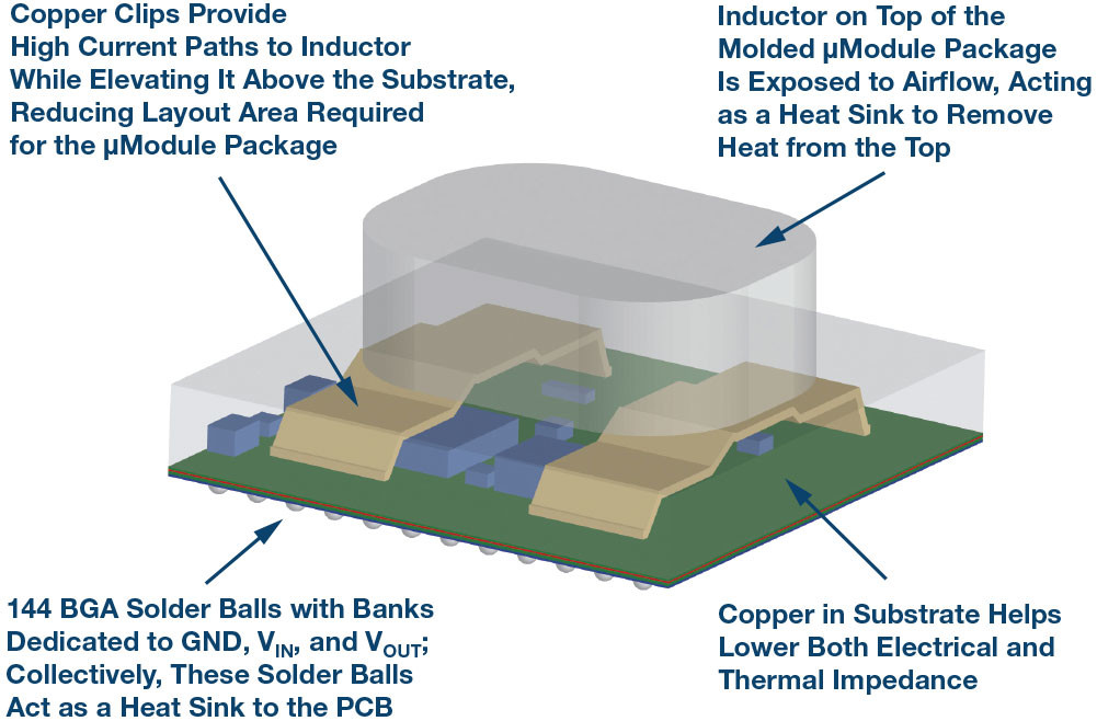
[Figure 1 | A high power POL regulator module uses 3D (vertical) pack- aging technology to elevate the inductor and expose it to airflow as a heat sink. The remaining DC-to-DC circuitry is assembled on the substrate under the inductor, minimizing required PCB area while improving thermal performance.]
3D packaging with exposed stacked inductor: Keep footprint small, increase power, and improve heat dissipation
A small PCB footprint, more power, and better thermal performance—all three are simultaneously possible with 3D packaging, a new method in construction of POL regulators (Figure 1). The LTM4636 is a µModule regulator with on-board, DC-to-DC regulator ICs, MOSFETs, supporting circuitry, and a large inductor to decrease output ripple and deliver load currents up to 40 A from 12 V input to precisely regulated output voltages ranging from 0.6 V to 3.3 V. Four LTM4636 devices running in parallel can current share to provide 160 A of load current. The footprint of the package is only 16 mm × 16 mm. Another regulator in the family, the LTM4636-1, detects overtemperature and input/output overvoltage conditions and can trip an upstream power supply or circuit breaker to protect itself and its load.
Horsepower advocates can calculate the power density of the LTM4636 and safely tout its numbers as impressive—but as previously discussed, power density numbers tell an incomplete story. There are other significant benefits that this µModule regulator brings to the system designer’s toolbox: superior thermal performance resulting from impressive DC-to-DC conversion efficiency and an unparalleled ability to disperse heat.
To minimize the regulator’s footprint (16 mm × 16 mm BGA), the inductor is elevated and secured on two copper lead frame structures so that other circuit components (diodes, resistors, MOSFETs, capacitors, DC-to-DC ICs) can be soldered under it on the substrate. If the inductor is placed on the substrate, the µModule regulator can easily occupy more than 1225 mm2 of PCB, instead of a small 256 mm2 footprint (Figure 2).

[Figure 2 | The LTM4636’s stacked inductor doubles as a heat sink to achieve impressive thermal performance in a complete POL solution with a small footprint.]
Stacked inductor construction rewards system designers with a compact POL regulator with the additional benefit of superior thermal performance. The stacked inductor in the LTM4636 is not overmolded (encapsulated) with plastic, unlike the rest of the components. Instead, it is exposed directly to airflow. The shape of the inductor casing incorporates rounded corners for improved aerodynamics (minimal flow blockage).
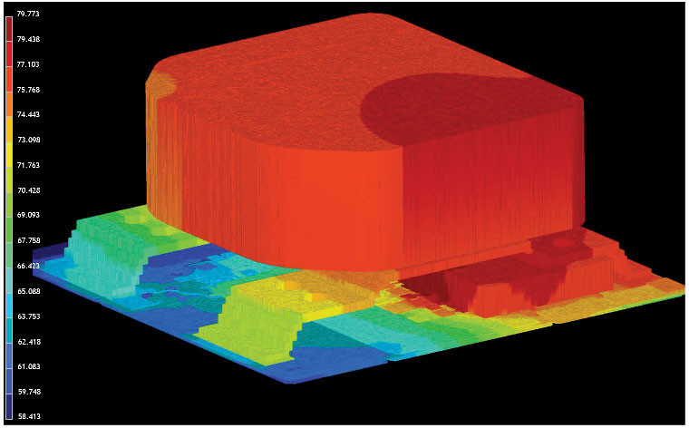
[Figure 3 | The modeled thermal behavior of LTM4636 shows heat is readily moved to the inductor package, which is exposed to airflow.]
Thermal performance and efficiency
The LTM4636 is a 40 A capable µModule regulator benefiting from 3D packaging technology, or component-on-package (CoP), as shown in Figure 1. The body of the package is an overmolded 16 mm × 16 mm × 1.91 mm BGA package. With the inductor stacked on top of the molded section, the LTM4636’s total package height, from the bottom of BGA solder balls (144 of them) to the top of the inductor, is 7.16 mm.
In addition to dissipating heat from the top, the LTM4636 is designed to efficiently disperse heat from the bottom of the package to the PCB. It has 144 BGA solder balls with banks dedicated to GND, VIN, and VOUT where high current flows. Collectively, these solder balls act as a heat sink to the PCB. The LTM4636 is optimized to dissipate heat from both the top and bottom of the package, as shown in Figure 3.
Even operating with a significant conversion ratio, 12 V input/1 V output, and at a full load current of 40 A (40 W) and standard 200 LFM airflow, the LTM4636 package temperature rises only 40°C over ambient temperature (25°C to 26.5°C). Figure 4 shows the thermal image of the LTM4636 under these conditions.
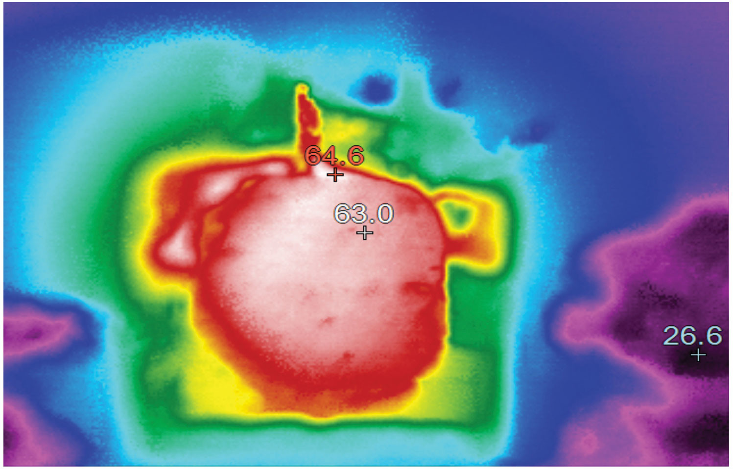
[Figure 4 | Thermal results of regulator at 40 W shows a temperature rise of only 40°C.]
Figure 5 shows the output current thermal derating results. At 200 LFM, the LTM4636 delivers an impressive full current of 40 A up to an 83°C ambient temperature. Half-current, 20 A derating only occurs at an excessively high ambient temperature of 110°C. This allows the LTM4636 to perform at high capacity as long as some airflow is available.
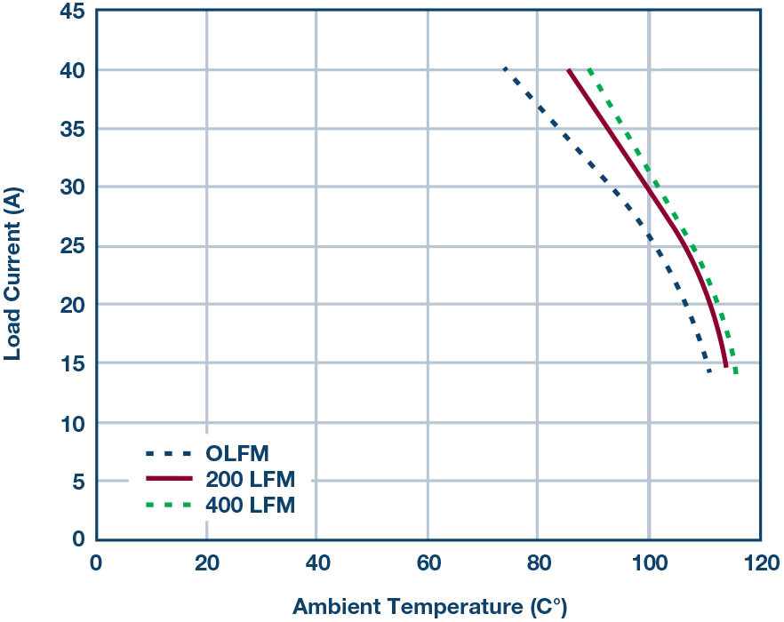
[Figure 5 | Thermal derating shows full current of 40 A delivered up to 83°C ambient, 200 LFM.]
The high conversion efficiency shown in Figure 6 is mainly a result of top performing MOSFETs and strong drivers of the LTM4636. For example, a 12 V input supply step-down DC-to-DC controller achieves:
- 5% for 12 V input to 3.3 V, 25 A
- 93% for 12 V input to 1.8 V, 40 A
- 88% for 12 V input to 1 V, 40 A
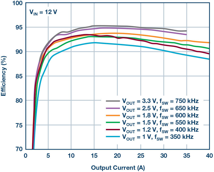
[Figure 6 | High DC-to-DC conversion efficiency over a variety of output voltages.]
140 W, scalable 4 A × 40 A µModule POL pegulator with thermal balance
One LTM4636 is rated for 40 A load current delivery. Two LTM4636s in current sharing mode (or parallel) can support 80 A, while four will support 160 A. Upscaling a power supply with parallel LTM4636s is easy; simply copy and paste the single-regulator footprint, as shown in Figure 7 (symbols and footprints are available).
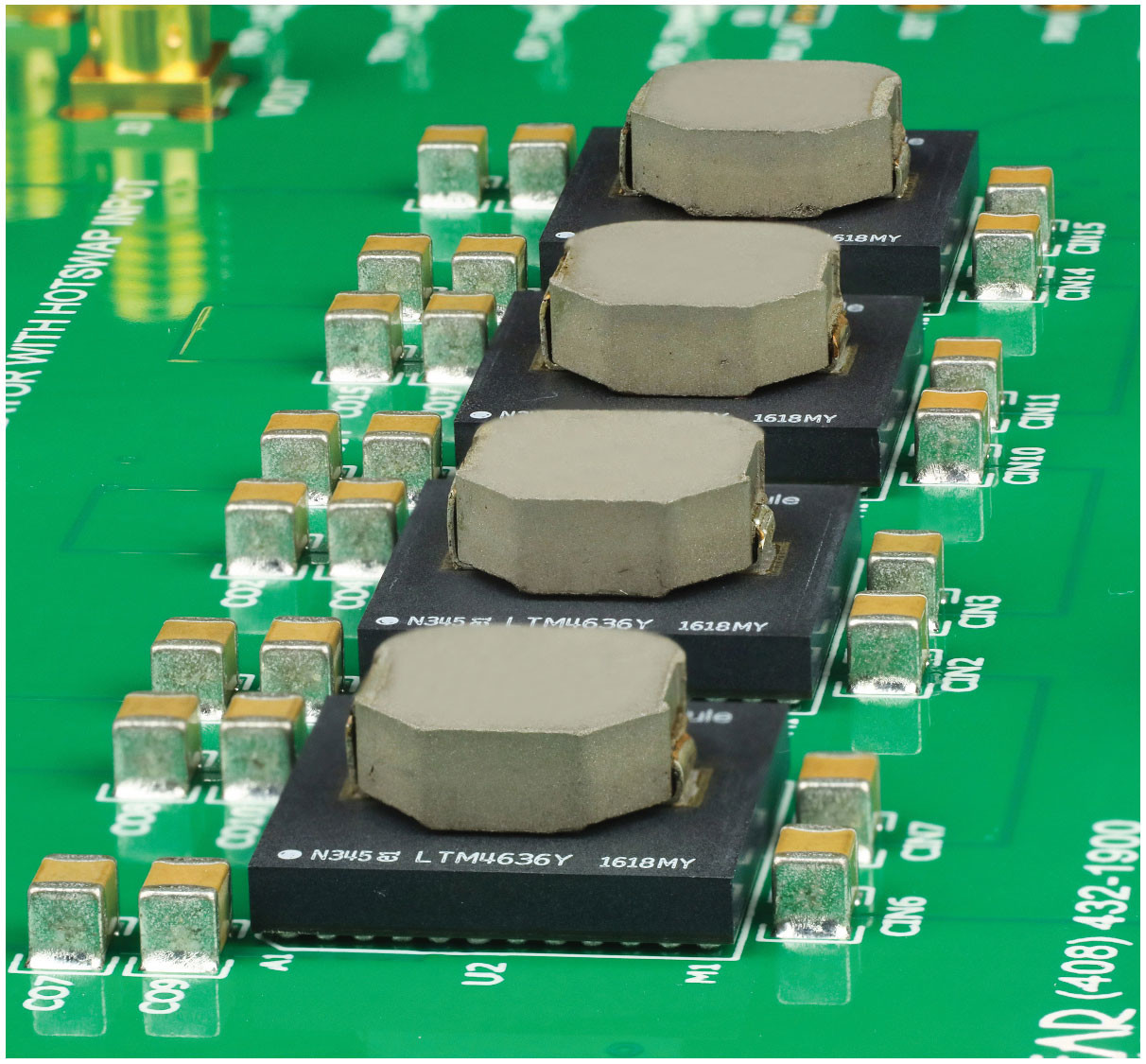
[Figure 7 | It is easy to lay out parallel LTM4636s. Simply duplicate the layout of one channel.]
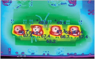
The current mode architecture of the LTM4636 enables precision current sharing among the 40 A blocks. Precise current sharing, in turn, produces a power supply that spreads the heat evenly between devices. Figure 8 shows a 160 A regulator with four µModules. All devices with these specifications operate within a °C of each other, ensuring that no individual device is overloaded or overheated. This greatly simplifies heat mitigation.
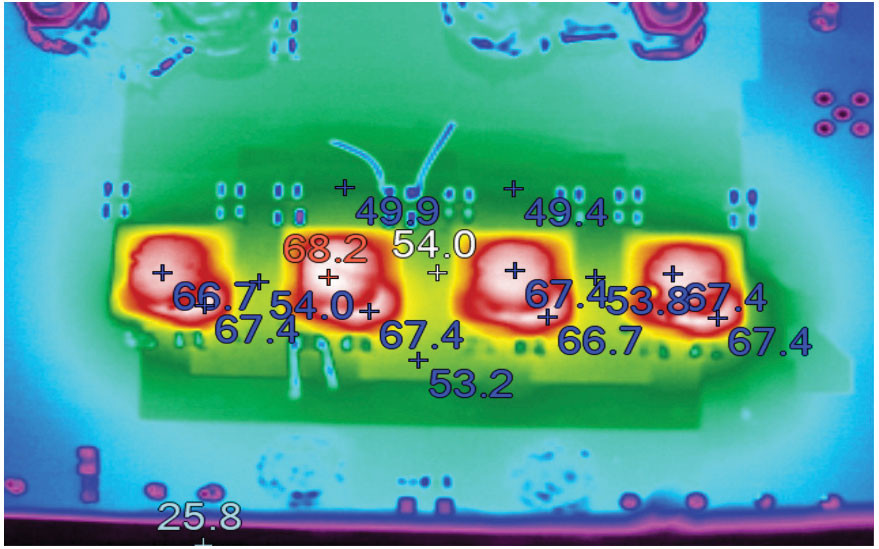
[Figure 8 | Precision current sharing among four LTM4636s running in parallel, resulting in only a 40°C rise in temperature for a 160 A application.]
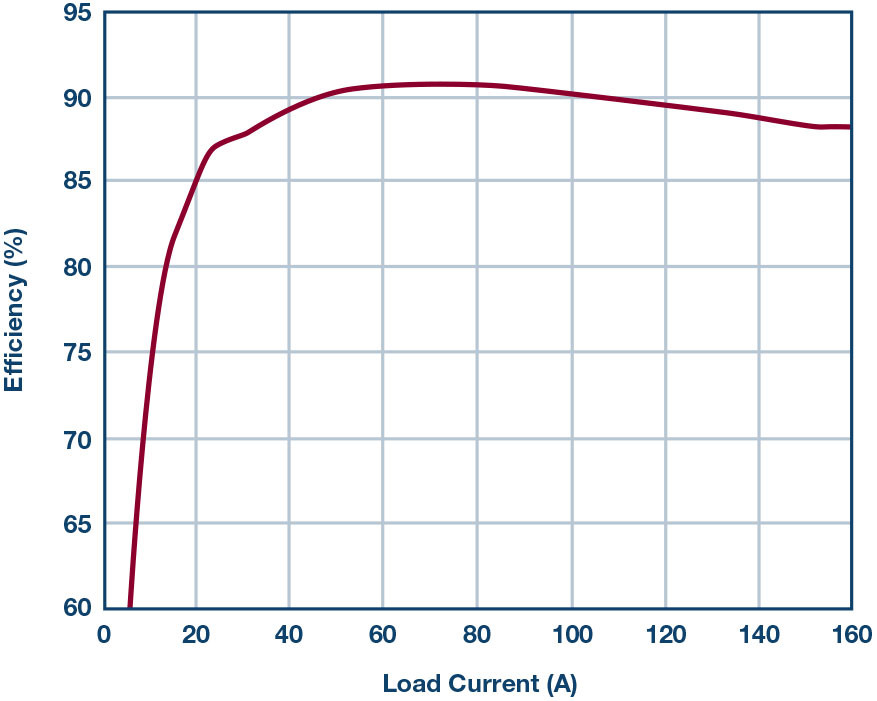
[Figure 9 | Efficiency of a 140 W regulator with four µModules.]
Figure 10 shows the complete 160 A design. Note that no clock device is required for the LTM4636s to operate out-of-phase respective of each other—clocking and phase control is included. Multiphase operation reduces output and input ripple current, reducing the number of required input and output capacitors. Here, the four LTM4636s in Figure 10 are running 90° out-of-phase.
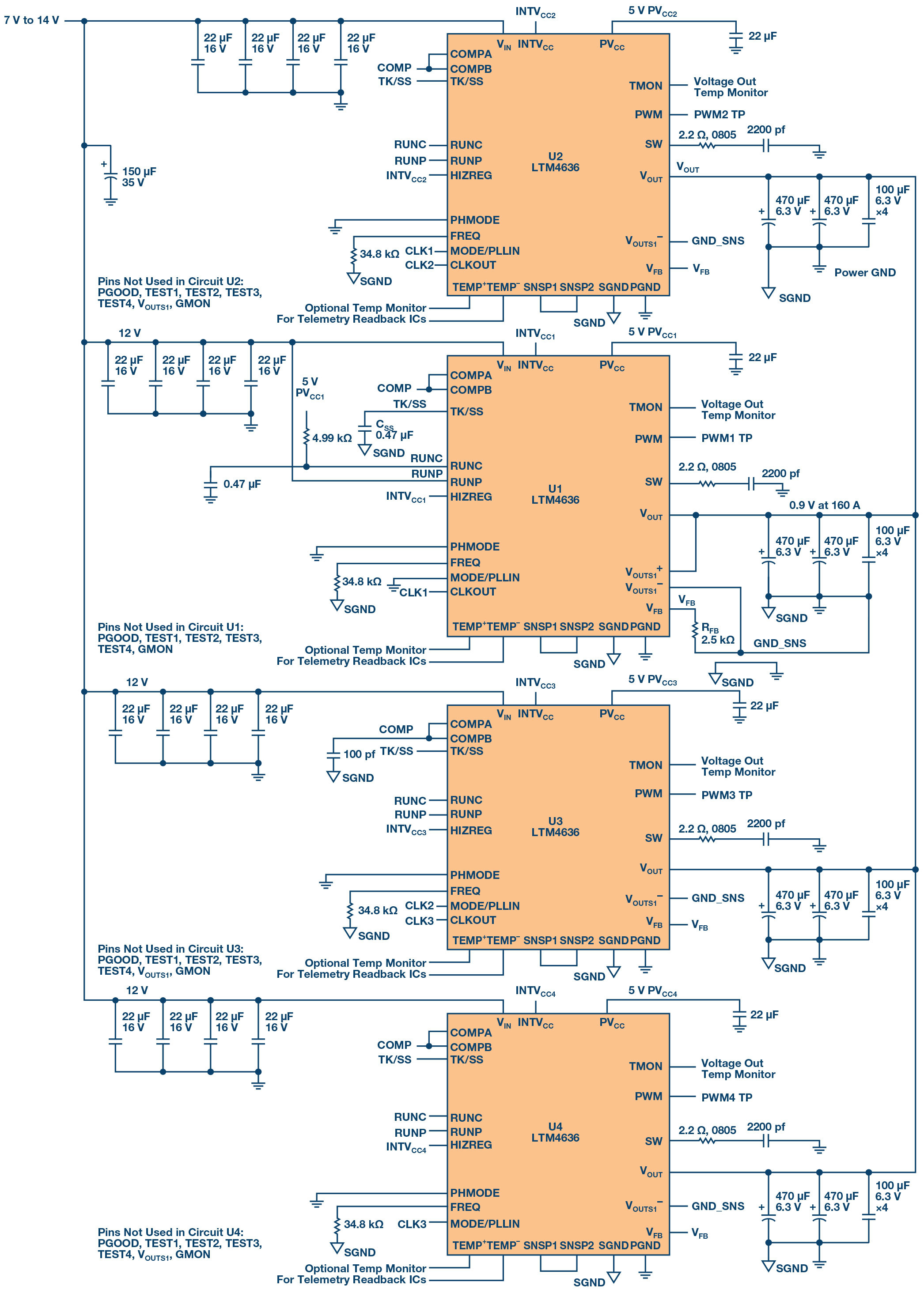
[Figure 10 | This 140 W regulator features four LTM4636s running in parallel with precision current sharing and high efficiency 12 V input to 0.9 V output at 160 A.]
Conclusion
Choosing a POL regulator for a densely populated system requires scrutiny beyond the voltage and amperage ratings of the device. Evaluation of its package’s thermal characteristics is essential, as it determines the cost of cooling, cost of the PCB, and final product size. Advances in 3D, also referred to as stacked, vertical, CoP allow high power POL module regulators to fit a small PCB footprint, but, more importantly, enable efficient cooling. The LTM4636 is the first series of µModule regulators to benefit from this stacked packaging technology. As a 40 A POL µModule regulator with a stacked inductor as a heat sink, it boasts 95% to 88% efficiency, with only a 40°C rise at full load, occupying only 16 mm × 16 mm of PCB area.