
Designing more flexible power banks with USB Type-C PD
July 12, 2018
Blog
This article discusses the design of USB Type-C PD power banks; i.e., power bank with a USB Type-C connector and using the USB Power Delivery (PD) specification.
The need for hand-held portable power sources has been driven by rapid growth in the use of smart phones, tablets, and other portable devices. According to the market research, the power bank market is expected to reach more than $25 billion by 2022. USB-based designs are the most popular among power bank designs.
The USB specification was defined, in mid 1990s, as a communication protocol for connecting external peripherals to a personal computer. In early 2000s as more and more portable devices were introduced into the market, powering them became a critical factor. The USB standard had significant advantages in the portable market due to its ability to transfer data and power with the same physical connector. However, USB powering methods were not reliable until the introduction of USB Battery Charging (BC) specifications.
Before the introduction of BC 1.0 specifications, the USB Standard Downstream Port (SDP) was used to supply a maximum of 100mA by default and 500mA when it is configured by power negotiation, which is defined by the USB 2.0 standard introduced in 2000. The first Battery Charging specification (BC 1.0), released in 2007, extended the maximum current limit for a Dedicated Charging Port (DCP) to 1.5A. In 2010, the BC 1.2 specification were released, increasing the maximum current limit to 5A. The latest USB Power Delivery (PD) specification extended the power delivery capability up to 100W with USB Type-C connectors.
The major percentage of smart phones, tablets, computer peripherals and portable devices have USB connectors and cables for powering. This article discusses the design of USB Type-C PD power banks; i.e., power bank with a USB Type-C connector and using the USB Power Delivery (PD) specification.
Design of conventional USB power banks
Power banks commonly use lithium ion batteries due to their high power density, light weight, lower self-discharge rate, and low maintenance cost. Table 1 shows the nominal voltage rating of lithium cells in 1-cell and 2-cell configurations. Generally, for power bank applications, the 2-cell configuration is recommended as the efficiency is higher.

[Table 1 | Nominal voltage of cell/battery.]
A conventional USB Power Bank design (see Figure 1), consists of two USB ports: the battery charging port and the battery discharging port (or output port).

[Figure 1 | Block diagram of a conventional USB power bank.]
The battery charging port in most designs is a USB Mini-B or Micro-B connector, which in turn is connected to a USB wall power adapter. The battery discharging port usually is a USB Type-A connector, where a smart phone or any other portable device is connected.
The battery charging subsystem consists of a USB Mini-B or Micro-B connector, buck-boost converter, battery parameter measurement circuit and the system MCU. The charging profile of a lithium ion battery consists of a constant current stage and a constant voltage stage to ensure efficient and safe charging up to the maximum capacity of the battery. The MCU controls the buck-boost converter that regulates the charging current for the battery. The MCU has a charging profile control block that handles current and voltage profiles based on the charging algorithm. The MCU also monitors and controls these charging profiles for the battery to avoid over charging and overheating that can cause the battery to explode.
Battery discharging section is also controlled by the MCU. The battery parameter measurement circuit provides battery voltage, discharging current, and temperature data to the MCU, which in turn handles battery discharge based on the battery-discharging algorithm. The MCU also controls the output buck-boost converter to provide power to an external device on the output port.
The MCU/controller generates all the signals required to control charging and discharging control circuits, read the parameter values from the measurement circuit, ensure the safety of the battery, and various other functionalities.
The move to USB Type-C Power Delivery
The application of a conventional USB power bank has been primarily for devices like smart phones, tablets and other portable devices that can be satisfactorily charged with 5V. Today’s power banks also need to be able to charge laptops, home appliances, and other devices that require a higher output voltage, higher current, and higher power rating. The manufacturers of various portable devices and smartphones have also introduced customized charging standards for more efficient charging.
For example, Apple Charging, Qualcomm Quick Charge (QC), Samsung Adaptive Fast Charging (AFC), and Programmable Power Supply (PPS) are some of the improved charging methods used in the smart phones. The voltage rating, current rating, and charging profiles of these methods are proprietary and no longer limited to 5V output. These charging protocols are different from legacy BC1.2 specifications and have an extended power rating.
The importance of USB Type-C PD power bank is clear when power banks are required to extend their support to other proprietary charging standards. The USB Type-C PD standard supports up to 20V/5A (100W) of power delivery, which is more than enough to power desktop computers, laptops, smart phones, tablets, other portable devices, and more.
Type-C connectors have already started taking over the smart phone and tablet industry, not only as a power connector but also as the data port and audio jacks. The Type-C connector has known advantages like:
- Reversible connector: Type-C solves the connector orientation issues that exist with legacy versions of USB connectors. Symmetrical connector pin alignment allows users to insert the connector in either way, thus increasing ease-of-use.
- Extended power handling capabilities: The Type-C connector can handle up to 100W of power. Type-C cables also are capable of handling 3A typically (up to 5A for active cables) of current without a significant drop across them.
- Alternate mode support: The additional pins can be configured for alternate mode support using Vendor Defined Messages (VDM) through the Configuration Channel (CC). The Type-C connector supports Display Port, HDMI, and other high-speed interfaces in alternate mode.
- Legacy USB D+ and D- lines: Type-C connectors are backwards compatible with previous USB standards back to USB 2.0, since D+ and D- lines are available. Two set of USB 2.0 signal pins are defined to enable the cable-flipping feature.
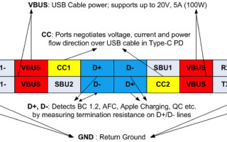
The pin diagram of a standard 24-pin Type-C connector is shown in Figure 2. Pins required for the implementation of a power bank application are also indicated.
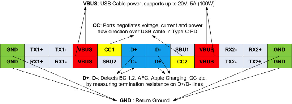
[Figure 2 | Standard Type-C Connector pin diagram.]
The D+ and D- pins detect various terminations on the connected device (phone, tablet, laptop, etc.) and identify the charging method used by the device. The power contract (i.e., voltage and current value) depends on the charging method or protocol, so termination detection is very important for power bank performance.
Configuration Channel (CC) pins are used in the discovery, management, and configurations of USB Type-C connections across the standard Type-C cable. During power delivery, CC lines (CC1, CC2) serve as additional function:Power negotiation. The attached ports negotiate voltage, current, and direction of power flow over the USB cable using the CC lines. The VBUS lines supply power according to the established contract after negotiation.
The most significant advantage of using USB Type-C for power bank design is its flexibility and ability to support different charging methods with single connector. Table 2 shows a comparative analysis between a conventional USB and USB Type-C PD power bank.

[Table 2 | Comparison between Power Banks based on Conventional USB and USB Type-C PD]
As can be seen from Table 2, the USB Type-C PD power bank offers superior functional due to its advantages of a reversible Type-C connector and its ability to support multiple charging protocols.
Design of USB Type-C PD power bank
Figure 3 shows the block diagram of a typical USB Type-C power bank. The Type-C power bank has a single Type-C connector interface for charging and discharging the Li-ion battery. The Type-C PD controller is the heart of the power bank and manages the buck-boost regulator controlling charge and discharge of the Li-ion battery.

[Figure 3 | Block diagram of USB Type-C PD power bank.]
Power bank operation supports two operations with a single Type-C connector: battery charging and battery discharging.
During battery charging, the Type-C PD controller enables consumer path FETs so that the Li-ion battery starts charging. The bi-directional buck-boost converter controls the battery charging voltage and current to maintain the correct charging profile. The Type-C PD controller continuously monitors battery parameters for safe and secure charging of the Li-ion battery.
During battery discharging or output, the Type-C PD controller turns on provider path FETs, and the Power Bank act as power source. The Type-C PD controller does power negotiation with the smartphone or device connected by the Type-C connector. It then controls the direction of the buck-boost regulator so that the Li-ion battery starts sourcing the current for charging the smartphone or other connected device.
Today, Type-C controllers are available that are designed specifically for the requirements of power bank and power adapter applications. For example, EZ-PD CCG3PA controllers from Cypress Semiconductor support the USB PD 3.0 specification with Programmable Power Supply (PPS) mode. The controller also supports legacy BC1.2 and various proprietary charging methods like Qualcomm Quick Charge (QC), Samsung Adaptive Fast Charging (AFC) and Apple charging.
Integrated controllers are built in important system-level protections that include overvoltage protection (OVP), overcurrent protection (OCP), under voltage protection (UVP), short circuit protection (SCP), over temperature protection (OTP), and electrostatic discharge (ESD) protection. Integrated configurable resistors and terminations on D+/D- lines further simplify design. For the most flexibility, controllers are available that support both Type-C and legacy Type-A ports so that power banks can interoperate with devices as the market transitions from Type-A to Type-C. System cost is reduced by integration of components such as VBUS voltage regulator, current sense amplifier, feedback control, ADCs, PWMs, and other functionality. Figure 4 shows a sample layout for power bank and adapter applications based on the CY4532 Evaluation kit using the CCG3PA controller.

[Figure 4 | Sample layout for power bank and adapter applications based on the CY4532 Evaluation kit using the CCG3PA controller.]
With a programmable controller, the power bank can support multiple charging standards, as shown in Table 3. Figure 5 shows an example of power bank operation.

[Table 3 | Programmable controllers can support multiple charging standards.]

[Figure 5 | Flow chart illustration example of power bank operation.]
USB Type-C PD is fast becoming the standard for portable devices and other applications. A comparative analysis between conventional USB power banks and USB Type-C power bank clearly shows that power banks based on USB Type-C PD represent the future for USB-based charging.


