
A lesson in wireless engineering from the Raspberry Pi
April 18, 2018
Product

How did the engineers behind the Raspberry Pi Zero W tackle antenna design, given its compact size, its low cost, and its mission of being usable by even novice computer science students?
Customers today expect smart products to be portable, compact, aesthetically-pleasing – and able to be connected anywhere and anytime. That is true for all products nowadays, but especially for consumer products where users expect a sleek look and feel without sacrificing any of the connectivity and performance they expect. Putting a check mark next to that entire wish list is challenging for product engineers, though, because of the inherent tension between a small, aesthetically-pleasing product and robust connectivity.
It takes a very careful balance between an antenna’s size, design, and performance to meet customers’ needs while also matching their stylistic preferences for the products’ overall design. As a rule of thumb, the larger the antenna is, the better its wireless range will be – but with that better performance comes challenges about how to make it work for the product you are designing. Finding the right balance is critical for every engineer, but navigating that tradeoff between antenna size and performance gets more challenging each year. The marketing specifications for new products dictate a design that is more compact than the last generation without sacrificing the wireless range. Unfortunately, making an antenna small and hidden are the two mortal enemies of antenna performance.
I am always curious whenever I look at a small antenna in popular consumer products because I want to know how well the antenna designer was able to get it to perform. Take the Raspberry Pi Zero W, for example, which has the same antenna as the newest version of Raspberry Pi announced in March. As an antenna enthusiast, I was drawn to the Zero W model of the Raspberry Pi because of its tiny and sleek antenna design used for WiFi and Bluetooth. How did the engineers behind the Raspberry Pi Zero W tackle antenna design, given its compact size, its low cost, and its mission of being usable by even novice computer science students?

The Zero W antenna is the trapezoidal shape located between the mini HDMI and micro USB sockets on the bottom edge of the board (Figure 1). As explained by Roger Thornton, Principal Hardware Engineer at the Raspberry Pi Foundation, “The Zero W antenna is a resonant cavity which is formed by etching away copper on each layer of the PCB structure.”
Given its small size and interesting shape of the Pi Zero W antenna, I had my doubts on how well the antenna actually worked. Luckily, as an antenna design engineer, I have access to an antenna chamber so I can measure it in the lab.
Antennas 101 – without the math
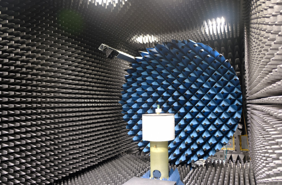
Antennas, like the one on the Zero W, are measured in a specialized test room called—not surprisingly—an antenna chamber. The room is specialized in a few key ways:
First, the antenna chamber is designed in a way that no wireless energy from the outside can get it, and no wireless energy from inside can get out. It essentially acts kind of like an electric bunker. In the wireless industry, we call this a Faraday cage. Second, the walls of the Faraday cage are lined with pyramidal shaped, RF absorbing foam. These foam pyramids are important because they prevent any wireless reflections from distorting the antenna measurements. Third, the antenna is positioned on a raised, foam pedestal that can rotate a full 360°. This allows us to measure a 3D radiation pattern.
When we press the ‘GO’ button on the antenna measurement in the chamber, you can expect back two measurement results that describe how well the antenna is working, which includes an analysis of antenna efficiency and the 3D radiation pattern.
Antenna efficiency answers the question, “How much wireless energy is actually radiated from the antenna?” The efficiency is described as a negative decibel (dB) value. The closer the antenna efficiency is to 0 dB, the better the antenna is. As a rule of thumb, an embedded antenna with an efficiency of -3dB or better is considered to be a great antenna.
The radiation pattern is a 3D visual that answers the question, “Where is the wireless energy going?” Is it going up, down, left, or right? This is a graphic that is compiled from hundreds of measurement points in the custom antenna chamber.
The first thing I measured in the chamber was the Zero W’s radiation pattern. Figure 3 illustrates the measured radiation patterns of the Pi Zero W’s antenna superimposed over the Raspberry Pi circuit board. On the radiation patterns, red indicates more energy in that direction (great wireless range) while blue means that little to no energy is radiated (limited wireless range).
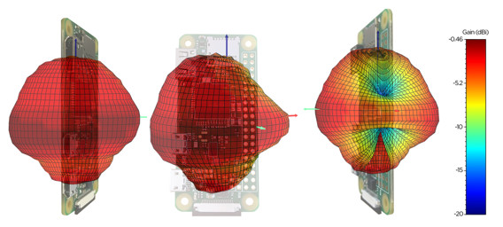
Overall, I am impressed with the quality of the radiation pattern. After looking at the visuals, you might react by saying, “Wait a minute. I thought the ‘blue’ sections would limit the WiFi range!” Luckily, in the real world, especially indoors, these poor parts of the radiation pattern are not a concern as the wireless signals in your home will reflect off walls and floors and the reflections will be received by the Raspberry Pi Zero W.
The second antenna parameter that was measured in the antenna chamber was the antenna efficiency vs. frequency. Since WiFi uses frequencies between 2400-2483.5 MHz in the United States, the efficiency at those frequencies is all that matters.
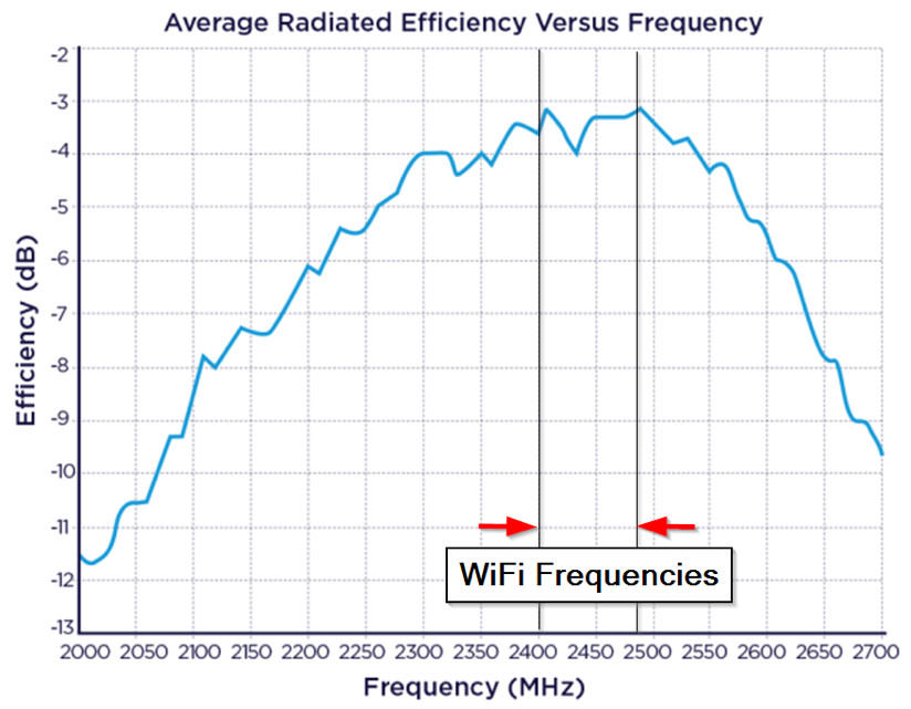
The radiated efficiency of the Pi Zero W antenna is measured to be -3.5dB efficient across the frequencies used for WiFi communication. While an antenna efficiency of -3.5dB may seem low at first glance, this is quite respectable for an embedded antenna of this size. To put that efficiency in perspective, a large 2.4 GHz dipole that you would find attached to a WiFi router would have a peak efficiency of -1.25dB.
With this clever trapezoidal antenna design, the Zero W only concedes 2.25 dB of antenna efficiency while reducing the maximum antenna dimension by 8x compared to a WiFi router antenna. That is remarkable. Remarkable not simply because of the small size of the Zero W’s antenna, but because the design adheres to the strict cost and simplicity objectives behind every aspect of Raspberry Pi. This is a great example of how those kinds of constraints can spark elegant engineering solutions.
So what does this mean for other electronic engineers? Well, for one thing, the Raspberry Pi Zero W’s antenna performs so well it could be adopted for a wide range of Wi-Fi applications as engineers work on wirelessly-enabled products.
Another key takeaway is to not judge a book by its cover when it comes to antennas. An unassuming antenna design might have surprising performance that makes it perfect for the product you are designing, but you may not know it until you put it into a chamber and measure its efficiency and radiation pattern.
The key is to test, either in your company’s own antenna chamber or by using an RF design company’s services. What you learn from these tests can help you select the right antenna, deploy it effectively within the product, and ensure the kind of performance that end users will expect. It is also important to note that the performance of embedded antennas like this are often significantly impacted by the components around it and the final design of the product. That can lead to a gap between the performance of the board design versus how it performs once it is in the final product. To ensure that the embedded antenna continues to meet expectations even once it is surrounded by other components and enclosed in the final product’s exterior form factor, it is important to work with an RF/wireless expert who can conduct the proper testing and assist with modifications that can achieve the performance end users are seeking. This can be the difference between a successful product and one that is a disappointment to users.
The last takeaway is the most important: You can always learn things from clever designs and smart engineers. The amount of effort and creativity that has gone into this $10 computer is impressive—and the results speak for themselves.


