A friendly introduction to XBee
November 30, 2017

Digi XBee radios sure are handy for wireless communication in embedded systems, so let?s take a look from a newbie perspective at how to quickly get two of them talking to each other.
Digi XBee radios sure are handy for wireless communication in embedded systems, so let’s take a look from a newbie perspective at how to quickly get two of them talking to each other.
This tutorial can be applied generically to any setup with any two XBee radios, so long as you have them plugged in and ready to work with a serial port. That being said, here is a list of parts used in this tutorial:
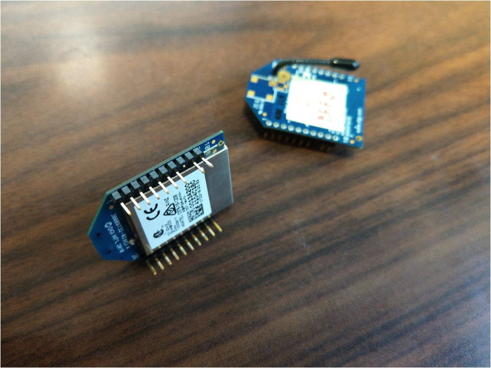
- 2x Digi XBee Pro (XBP24-AWI-001) radios
- Technologic Systems’ Part Number OP-XBEERADIO
- 1x SparkFun XBee Explorer USB
- 1x TS-7553-V2
- 1x USB Mini-B Cable
As far as software goes, we’re going to need to use the one and only Xbee programming tool, XCTU from Digi (compatible with Windows, Mac OS, and Linux). I suppose if you are hardcore you could program using raw AT commands in the console, but I doubt that’s a path you’re willing to take at this time!
We’ll start by installing the software, configuring the XBee radios, installing them, and finally getting them talking to each other.
Digi XCTU software
Installation of the Digi XCTU software should be straightforward enough. Head over to the XCTU download page, download it to your platform, and follow the install instructions.
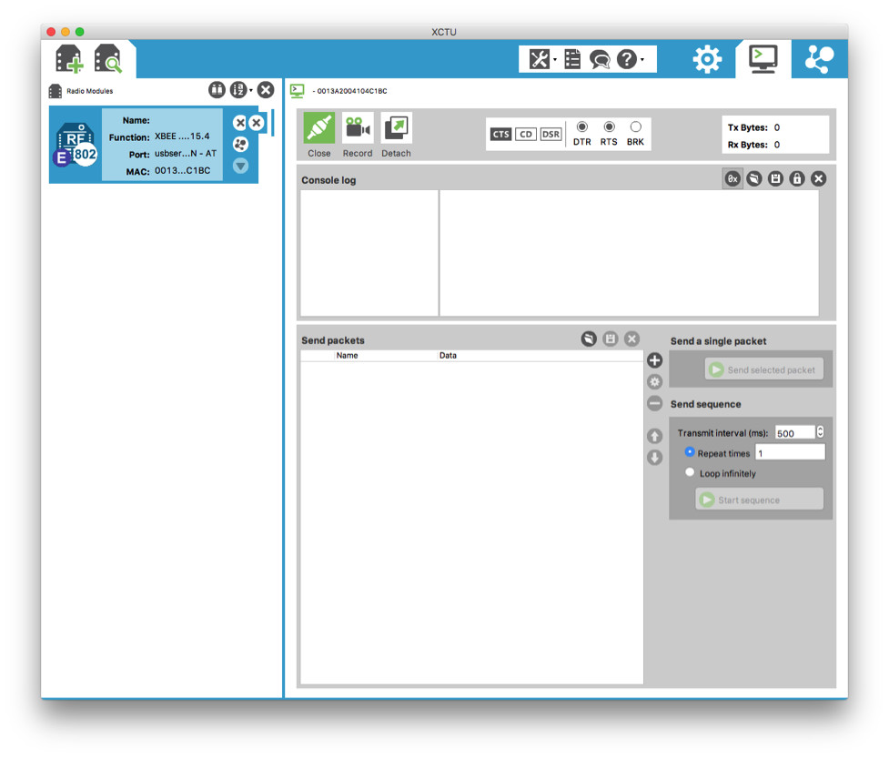
When you’ve installed it, open it up. Here’s what you should see:
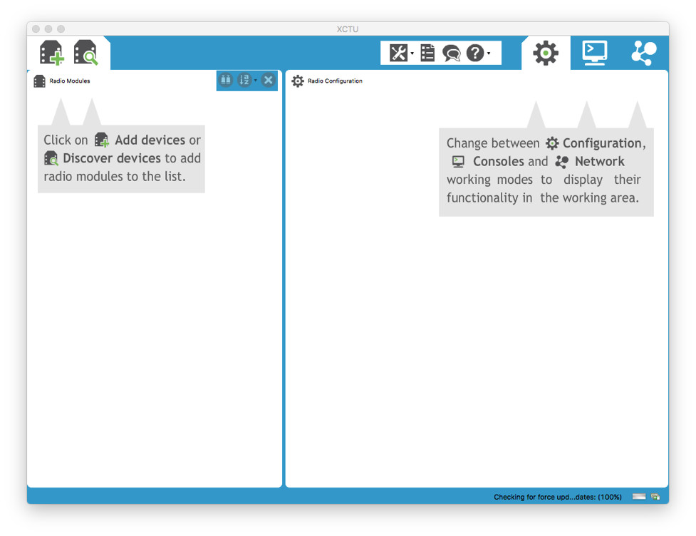

Okay! Now, we’ll move on to hooking up the XBee radios using the XBee explorer breakout board and configuring them using our newly installed XCTU program.
Configuring the XBee radios
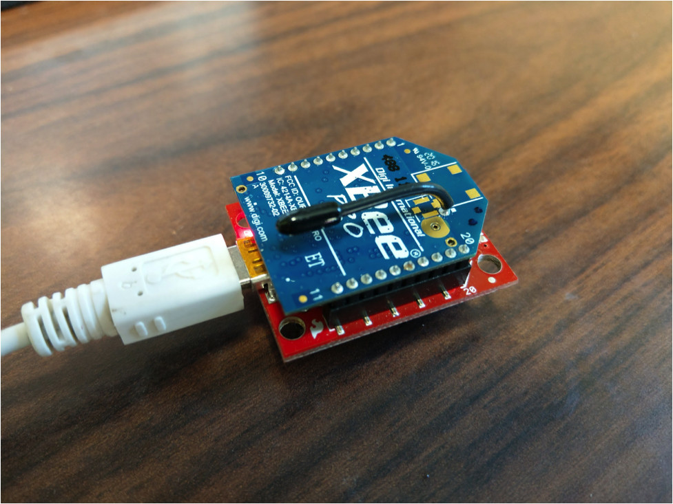
Here’s where the rubber meets the road! We’re going to break out the SparkFun XBee Explorer and program both of the XBee radios so they can talk to each other. All we need is a USB Mini-B cable to connect the XBee Explorer to our computer with XCTU installed. Grab one of the XBee radios and dock it on the XBee Explorer, then plug the USB cable connected to your computer into the XBee Explorer board.
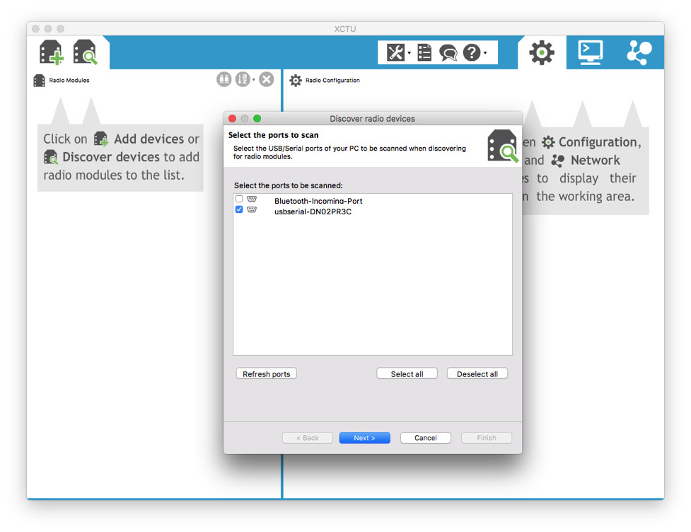
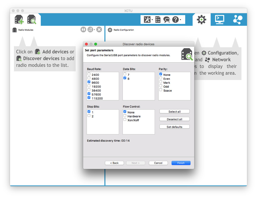
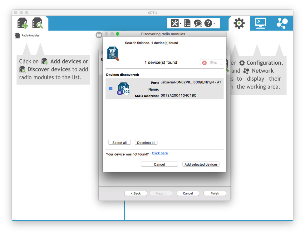
Once you’ve made the connections, open XCTU (if you haven’t already) and click on the “Discover devices” button. From here, you just have to scan the port plugged into the XBee Explorer.
Before continuing there are a couple of concepts and some terminology we’ll need to get familiar with.
- With an XBee network like we’re setting up, there needs to be a coordinator and an end device. You can think of this as having a router and a computer.
- Both of the radios need to be on the same channel and network, or personal area network (PAN) in this case.
- Every option is abbreviated with a two letter key. The ones we’re concerned with are:
- CH – Channel
- ID – PAN ID
- MY – 16-bit source address (this is the address of the device, which can be any 16-bit number)
- DL – Destination address low (DL is the address of the device you want to talk to, which can be any 16-bit number other than MY)
- CE – Coordinator enable
- BD – Interface data rate (optional)
- CT – AT command mode timeout (optional)
- XBee radios are programmed using AT commands over the serial console. The XCTU program makes programming the XBee incredibly easy as it takes care of running all the AT commands transparently in the background.
Tip: Save yourself headaches and label your XBee radios so you can tell them apart. A piece of tape or tiny post-it note and permanent marker will do just fine. Label one “C” for “Coordinator”, and the other "ED” for “End Device”. You can also write the MY 16-bit source address for extra clarity.
Program the coordinator
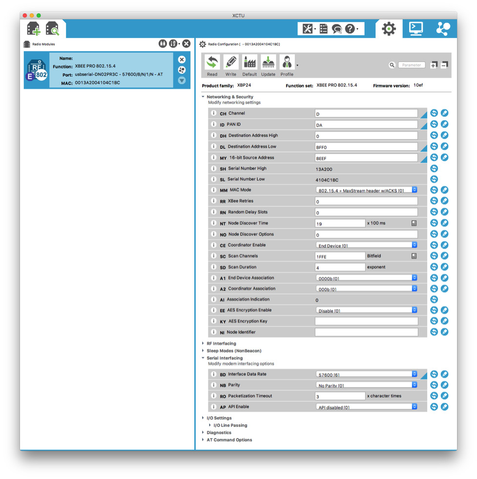
Let’s take the first XBee radio, which we’ll designate as our Coordinator (and will ultimately be installed in the TS-7553-V2) and open the “Configuration” window in XCTU. This is what you should be looking at:


Tip: XCTU is pretty well designed, with handy little UI gems like a blue ‘dog ear’ triangle to mark which settings have changed from defaults. Firmware updates, updating individual settings, and more come in pretty handy. Be sure to familiarize yourself when ready.
Here’s how we’re going to set our coordinator:
CH, Channel = D
ID, PAN ID = DA
DL, Destination Address Low = BEEF
MY, 16-bit Source Address = BFFO
CE, Coordinator Enable = Coordinator [1]
The following two configuration changes are optional, but they make things more responsive and run more smoothly in my experiences. If you do elect to change these setting, be sure to make the same changes on both XBee radios.
BD, Interface Data Rate = 57600 [6]
CT, AT Command Mode Timeout = 1770
Once you’ve set these configurations, make sure to click on the “Write” button to save the changes to the XBee radio. Once it’s finished writing, go ahead and unplug the XBee Explorer and take out the XBee radio.
Installing the coordinator
This is where the TS-7553-V2 comes into play. This tutorial assumes you’re already familiar with how to configure the TS-7553-V2 for development, but if you're not take a look at the “Practical Guide to Getting Started With the TS-7553-V2”.
There’s a XBee socket on the TS-7553-V2 that shows up under the /dev/ttymxc7 serial device. But before we can plug in our XBee radio, we need to remove or bend pin 8 of the XBee radio in order to avoid conflicts. This will be fixed in an upcoming version of the TS-7553-V2 .

Now, plugin the XBee radio we’ve designated as the coordinator like this:
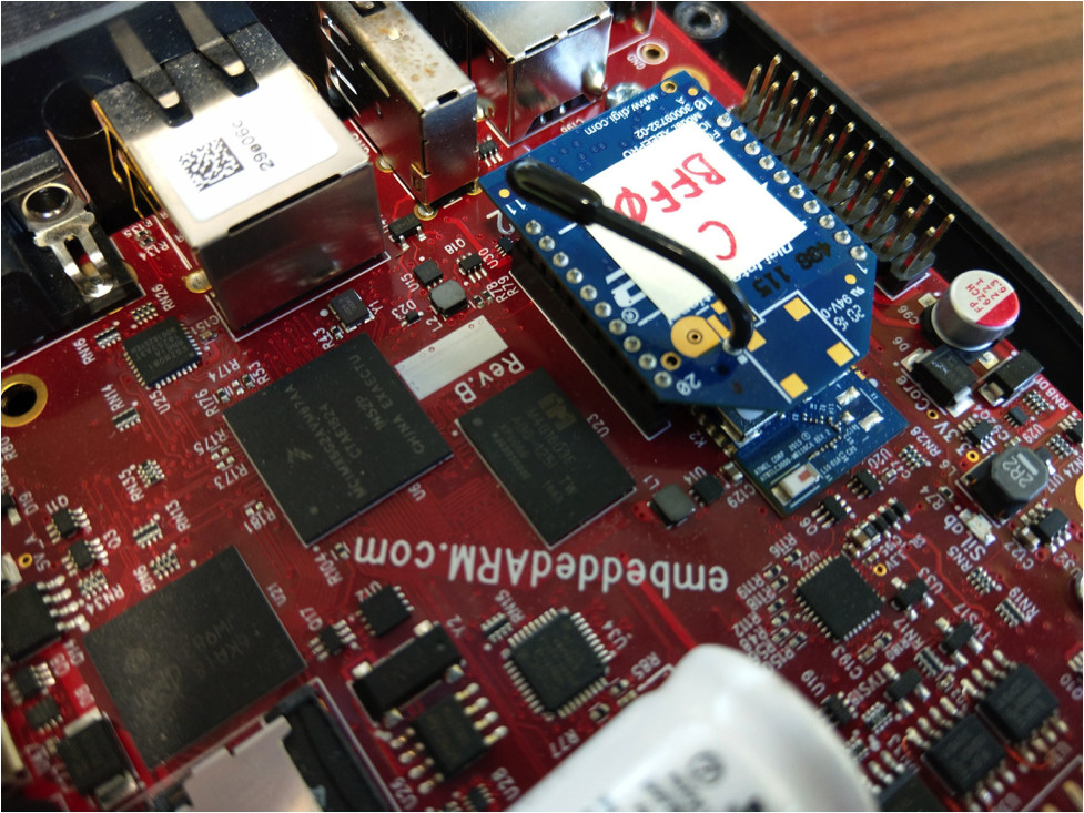
Tip: Make sure that the flat end of the XBee radio is facing back towards the USB and Ethernet connectors. Otherwise, you may do permanent damage to the XBee radio.
Next make sure that the XBee radio is powered on and ready to communicate. Issuing the following command will help you determine whether it’s turned on (it should be by default):
root@ts-imx6ul:~# echo 1 > /sys/class/leds/en-xbee-3v3/brightness
Then let’s open a serial connection with the XBee radio using picocom, making sure that the baud rate is set to the same value as BD, Interface Data Rate on the XBee radios.
root@ts-imx6ul:~# picocom -b 57600 /dev/ttymxc7
Perfect! Now, we’re ready for the next step.
Program the end device
Now, we’re going to install the second XBee radio into the XBee Explorer and plug the XBee Explorer into the computer. We’re going to designate this radio as our End Device. As before, click on the “Add devices” or “Discover devices” buttons to find your device and load the “Configuration” window, like so:
 Here’s what we’re going to set on our end device:
CH, Channel = D
ID, PAN ID = DA
DL, Destination Address Low = BFF0
MY, 16-bit Source Address = BEEF
CE, Coordinator Enable = End Device [0]
Again, these are optional, but they must be the same on both devices.
BD, Interface Data Rate = 57600 [6]
CT, AT Command Mode Timeout = 1770
Great! Now, we’re going to leave this one plugged into the XBee Explorer for the next step.
Time to start talking!
Now, the exciting part: Communicating wirelessly over a serial port provided by the XBee radio.
We start off by going back to our XCTU program and opening the “Console” window, like so:

We’re now going to send a packet from our end device to the coordinator installed in our TS-7553-V2. Click on the plus icon (+) next to the “Send packets” field. Here, type in your ASCII message (something as simple as “Testing” will work), and save the packet once finished. Next, select the new packet and click on the “Send selected packet” button.
Head over to the TS-7553-V2 picocom session you opened earlier and you should now see “Testing” written on the screen! In picocom, type something like “Testing back!”, and you should see the message being written in the Console log field of the XCTU program!
Congratulations on setting up your wireless serial console connection! You’re well on your way to creating something awesome using XBee radios!
Conclusion and Next Steps
In this guide, we walked through what it took to install, configure, and wirelessly transfer data between two XBee radios. Now that you have the basics out of the way, it’s time to dive into the world of XBee wireless with different topologies and configuration options.
If you have any further questions, or feel like we’ve forgotten to mention anything, please let me know in the comments!
Derek Hildreth is eBusiness Manager at Technologic Systems. Prior to his current role, Derek was an Applications Engineer for Oracle, and Embedded Systems Engineer at Technologic Systems.
Technologic Systems
LinkedIn: www.linkedin.com/company/technologic-systems
Facebook: www.facebook.com/embeddedARM
YouTube: www.youtube.com/user/embeddedarm
GitHub: github.com/embeddedarm