
Using a memory protection unit with an RTOS, part 4
June 04, 2018
Story

In this last installment of this series on using an RTOS with an MPU, we?ll look how you group RAM by process and conclude with a list of recommendations when using the Cortex-M MPU.
This is part four of a four-part series. Read the other parts here: Part 1, Part 2, and Part 3.
So far, we looked at what an MPU is and how it can help isolate tasks and processes from one another. We’ve also examined how to set up the Cortex-M MPU and found that it was quite easy to use. The complexity of using an MPU has more to do with organizing the memory of an application than the mechanics of updating this highly useful device.
In this last installment of this series on using an RTOS with an MPU, we’ll look how you group RAM by process and conclude with a list of recommendations when using the Cortex-M MPU.
Creating the MPU process tables
Probably the biggest difficulty when using an MPU is grouping memory by process and creating the MPU process table. This is partly because you need a more intimate understanding of your toolchain: compiler, assembler, and linker/locator.
Let’s assume I’m using the IAR toolchain (i.e. EWARM), but the concepts are similar enough that you’ll be able to adapt these for the tools you use. Unless otherwise directed, the linker will place data (i.e. RAM) in one of three sections illustrated in Figure 2.
- Uninitialized data
- Zero initialized data
- Initialized data
As the name implies, uninitialized data corresponds to variables that have not been given an initial value at compile time or are not declared static.
Zero initialized data corresponds to data that was declared static and gets initialized to zero at startup. The linker groups this as one contiguous block so that startup code can perform a block set (to 0).
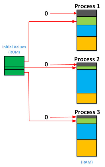
Initialized data corresponds to data that has an initial value (e.g. int x = 10;). Again, the linker groups this data into a contiguous block but creates a parallel block in ROM that contains the initial value of each of the corresponding variables in RAM. At startup, the whole block is copied from ROM to RAM.

[Figure 2 | RAM sections.]
As previously discussed, RAM for a process must be grouped continuously as shown in Figure 3. To accomplish this, we need to bypass the compiler/linker standard sections and create new sections that we will be grouped by process. The toolchains are typically capable of creating multiple blocks of zero and initialized sections as shown in Figure 3.
[Figure 3 | RAM sections for MPU-based application.]
Creating named RAM sections
To group data by process, we need to use the EWARM #pragma directive default_variable_attributes and wrap all the variables that are to be grouped together in a process.
#pragma default_variable_attributes = @”.Process1”
// All variables that we want to be part of the section named “.Process1”.
#pragma default_variable_attributes =
I+f your application contains variables declared in assembly language files, then you’ll also need to make sure the assembly language file contains the appropriate assembler directives.
Grouping RAM by blocks
Your application will surely contain code that is not necessarily associated with any specific process. In this case, it would be best to create named sections for those modules and then combine the sections into a common block of code. You would then use the #pragma directive described above to create different named sections, one for each module, and use the linker’s block directive as shown below to group these sections.
define block COMMON_RAM_BLOCK with alignment = 4K, size = 4K
{
section .DRIVER_RAM,
section .COMMOM_RAM,
section .MATH_RAM,
section .STRING_RAM,
}
define block PROCESS_AI_RAM_BLOCK with alignment = 16K, size = 16K
{
section .AI_DRIVER_RAM, // Analog input driver
section .RTD_LIN_RAM, // RTD linearization
section .THERMOCOUPLE_LIN_RAM, // Thermocouple linearization
section .UNIT_CONVERSION_RAM, // Shared RAM with AO module
}
define block PROCESS_AO_RAM_BLOCK with alignment = 8K, size = 8K
{
section .AO_DRIVER_RAM, // Analog output driver
section .4_20MA_LIN_RAM, // 4-20 mA linearization
section .ACTUATOR_LIN_RAM, // Actuator linearization
section .UNIT_CONVERSION_RAM, // Shared RAM with AI module
}
define block SHARED_RAM_BLOCK with alignment = 2K, size = 2K
{
}
You will note that the block directive allows you to specify the size and alignment of a memory block. It’s important that both values are the same in order to place the start address of the block in the MPU process table. Also, the amount of RAM needed for each block depends on the application. I decided to use 16K, 8K, 4K and 2K bytes for the sake of illustration.
Locating RAM blocks
We can now place all the blocks in the MCU’s addressable space using two linker directives: region and place:
define region RAM = Mem:[from 0x20000000 size 64K];
place in RAM
{
block RAM_ALL with fixed order
{
block PROCESS_AI_RAM_BLOCK,
block PROCESS_AO_RAM_BLOCK,
block COMMON_RAM_BLOCK,
block SHARED_RAM_BLOCK
}
}
The region directive specifies the addressable memory of the MCU. There could be different region directives if your RAM is not all contiguous.
The place in RAM directive specifies to locate the blocks in the RAM area. You will notice that we needed to put blocks within a block to specify the order of block placement. In fact, to reduce the amount of wasted space, larger blocks should go first.
Creating the MPU Process table for each task
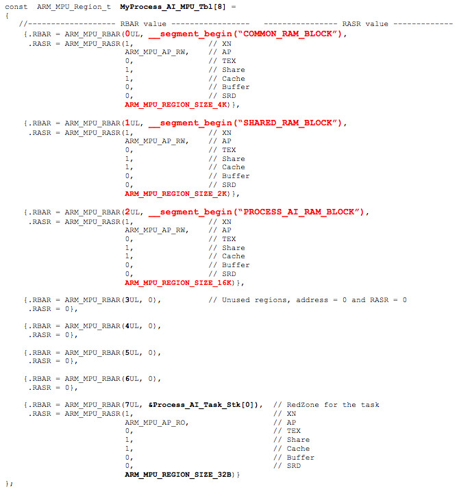
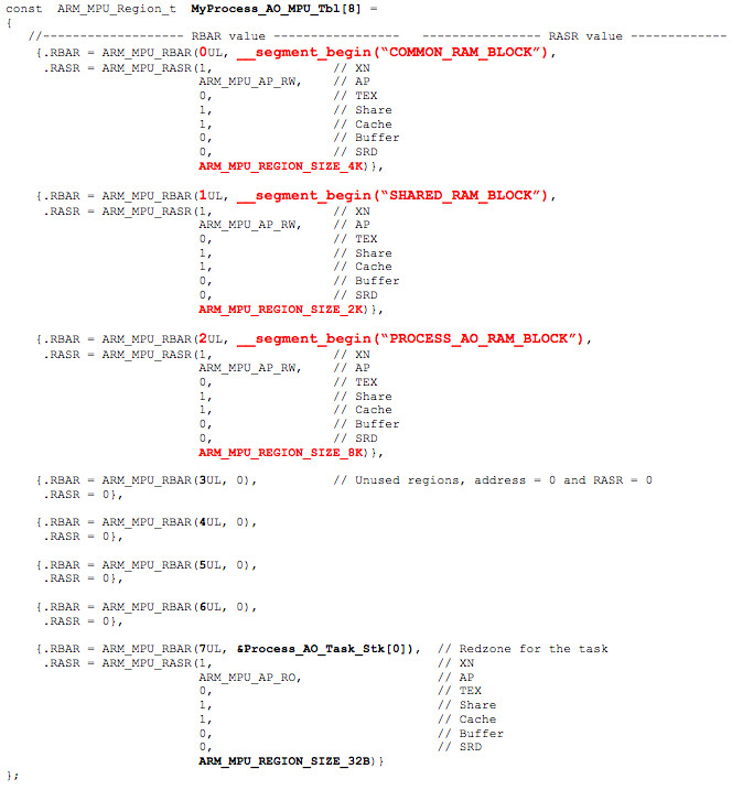
Now that RAM is grouped by process, you can go back and edit the MPU table for each task/process. However, to do this, the compiler must know the names of the blocks so, you will need to use the #pragma section directive as follows:
#pragma section = “COMMON_RAM_BLOCK”
#pragma section = “PROCESS_AI_RAM_BLOCK”
#pragma section = “PROCESS_AO_RAM_BLOCK”
#pragma section = “SHARED_RAM_BLOCK”
The two process tables can now look as follows (assuming you are not using the version that contains the per-task callback as described in the previous section):
Recommendations
Below are a few recommendations when using the Armv7-M MPU.
Run user code in non-privileged mode:
It’s possible to use the MPU and yet still run all the application code in privileged mode. Of course, this means that application code would be able to change the MPU settings and would thus defeat one of the purposes of having the MPU. Initially running the application in privileged mode might allow easier migration of your application code. At some point, though, most of your application code will need to run in non-privileged mode, and you will thus need to add the SVC handler.
Set PRIVDEFENA to 1:
This allows privileged code to have access to the full memory map. Ideally, most of your application will run in non-privileged mode, and only ISRs and the RTOS will run in privileged mode. This recommendation avoids consuming three MPU regions for every task to give privileged code access to any RAM location, any code and any peripheral device. The decision of setting PRIVDEFENA to 1 might already have been made by the RTOS supplier and not something you can change.
ISRs have full access:
The processor switches to privileged mode whenever an interrupt is recognized and the ISR starts. Since PRIVDEFENA would be set to 1, ISRs have access to any memory of I/O location anyway. You simply don’t want to reconfigure the MPU upon entering an ISR and reconfigure it back upon exit. So, ISRs should be considered system-level code and thus should indeed be allowed to have full access.
Also, ISRs should always be as short as possible and simply signal a task to perform most of the work needed by the interrupting device. Of course, this assumes that the ISR is kernel aware and the task has a fair amount of work dealing with the interrupting device. For example, processing an Ethernet packet should not be done at the ISR level. However, toggling an LED or updating the duty cycle of a pulse width modulation (PWM) timer might be done directly in the ISR.
Set the XN bit to 1:
The eXecute Never bit of the RASR register should be set for all RAM or peripheral regions if your application code is not expecting to execute code out of RAM. Setting the XN bit for peripheral devices may seem strange, but it doesn’t hurt and protects against hackers who would look at ways to get into your system.
Limit peripheral device access to its process:
You should set aside one or more MPU regions to limit access of a process to only its own peripherals. In other words, if a process manages USB ports, then it should only have access to USB peripherals or peripherals related to the needs of the USB controllers such as DMA.
Limit RTOS APIs:
The system designer needs to determine which RTOS API should be available to application code. Specifically, do you want to prevent application code from creating and deleting tasks or other RTOS objects like semaphores, queues, etc. after system initialization? In other words, should RTOS objects only be created at system startup but not during run-time? If so, then the SVC handler lookup table should only contain the APIs you want to expose to the application. However, even if ISRs run in privileged mode and thus have access to any of the RTOS APIs, a good RTOS would prevent creating and deleting RTOS objects from ISRs anyway.
Allocate RTOS objects in RTOS space:
Task stacks are located within a process’s memory space. However, RTOS objects (semaphores, queues, task control blocks, etc.) should preferably be allocated in kernel space and be accessed by reference. In other words, you don’t want to allocate RTOS objects in a process’s memory space because that would mean application code can, whether purposely or accidentally, modify these objects without passing through RTOS APIs.
No global heap:
It’s virtually impossible to set up an MPU to use a global heap (i.e., a heap used by all processes) so you should avoid those if at all possible. Instead, as previously suggested, you should allow process-specific heaps if a process requires dynamically allocated memory such as Ethernet frame buffers.
Don’t disable interrupts:
If your application runs in non-privileged mode, any attempt to disable interrupts will be ignored. The problem with this is that you will have no indication from the CPU that interrupts have not been disabled.
A bus fault will be triggered if your application runs in non-privileged mode and you attempt to disable interrupts through the NVIC.
Protect access to code:
Although MPU regions are generally used to provide or restrict access to RAM and peripheral devices, if you have spare regions and you are able to organize code (via linker commands) by processes then, it might be useful to limit code access to code. This prevents certain types of security attacks like Return-to-libc [2].
Reduce inter-process communications:
Just like tasks should be designed to be as independent as possible, processes should also follow the same rule. So, either processes don’t communicate with one another or you keep inter-process communication to a minimum.
If you have to communicate with other processes, simply set aside a shared region containing an out and an in buffer. The sender places its data in the out buffer and then triggers an interrupt to wake-up the receiving process. Once the data is processed, the response (if needed) can be placed in the in-buffer of the sender, and an interrupt can be used to notify the sender.
Determine what to do when you get an MPU fault:
Ideally, all MPU faults are detected and corrected during development. You should plan for faults to occur in the field either because of an unexpected failure or bug, or because your system was subjected to a security attack. In most cases, it’s recommended to have a controlled shutdown sequence for either each task or each process. Whether you restart the offending task, all tasks within a process or the whole system depends on the severity of the fault.
Have a way to log and report faults:
Ideally, you’d have a way to record (possibly to a file system) and display the cause of the fault to allow the developer(s) to fix the issue(s).
Conclusion
A Memory Protection Unit (MPU) is hardware that limits the access to memory and peripheral devices to only the code that needs to access those resources. If a task attempts to access a memory location or a peripheral device outside of its allotted space, then a CPU exception is triggered, and depending on the application, corrective actions must be taken.
The MPU found in a Cortex-M MCU is a fairly simple device and relatively easy to configure. However, the complexity in using the MPU is more oriented toward the allocation of storage (mostly RAM) by process and the creation of MPU process tables that will be loaded into the MPU during a context switch.
Finally, I provided a list of recommendations that would make better use of an MPU in your application.
Software alone cannot prevent access to memory or peripheral devices not assigned to tasks in an RTOS environment. You need hardware to accomplish this, and the MPU is currently the only mechanism available on the Cortex-M (Armv7-M) that can do that.
Migrating an application to use the MPU is a fairly easy but tedious process. Adding an MPU will also impose overhead on your application: you have additional registers to load during a context switch, and user code should run in non-privileged mode to avoid having such code alter the MPU settings.
References
- Jean J. Labrosse. "Detecting Stack Overflows". https://www.micrium.com/detecting-stack-overflows-part-1-of-2/, https://www.micrium.com/detecting-stack-overflows-part-2-of-2/.
- Wikipedia, “Return-to-libc attacks”. https://en.wikipedia.org/wiki/Return-to-libc_attack.


