
Networking with CAN FD ? have you also thought about testing?
September 18, 2017

With the flexible data rate and the thereby increased bandwidth, the raison d'?tre of CAN bus system architectures is significantly extended.
The introduction of new technologies in the automotive industry is a risk- and cost-intensive undertaking. Particularly in the area of vehicle networking, this often means a balance between proven mechanisms, growth of functions, and increased bandwidth thanks to more advanced bus systems. The reliability achieved over the past few years is always the standard and must not be put at risk under any circumstances. The demand for networking tests has enormously increased of late and represents a significant step in the approval process for hardware and software components of new vehicle generations.
The CAN bus has proven itself to be an efficient and robust communication medium to date. With the flexible data (FD) rate idea and the thereby increased bandwidth, the raison d'être of CAN bus system architectures is significantly extended. The changes in the log, the higher data lengths, and various bitrates require new or adapted test cases and test systems.

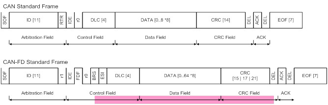
[Figure 1 | CAN frame layout]
Network test
The methods for testing the network functions of bus participants are defined in the specifications and testing standards of the individual OEMs.
Alongside the bus physics, various controller parameters such as bitrate and scanning time are to be tested. By assessing the bus communication, the transmit messages of the control unit are tested against the data definition (ID< DLC, cycle time, signal tests for counters, and checksums, for example).
Typical test cases include the determination of the working voltage limits, power consumption, and transmit start, as well as the reactions to faults in the working voltage in the form of pulses and ramps.
Testing the CAN error management represents a significant testing task in the CAN control unit test. For the inspection of the busoff handling, transmit messages of the control unit are disrupted and send and waiting phases, reinitialization, and readiness to receive in the waiting phases are evaluated. The test cases for network management conform to the network management type used (OSEK-NM, NMHigh, AutoSAR) and check state transitions and wake causes, upholding the idle bus and the timing, for example. The test complex of the onboard diagnosis contains, for example, the test of the transport log, the CAN error management (start of monitoring, voltage thresholds, message failure, signal errors, busoff), and the checking of the diagnosis service.
CAN FD interface test
CAN FD is essentially an expansion to the log level. That's why most of the points of the test specifications for classic CAN are also valid for CAN FD. Several features or test cases to be additionally carried out should be briefly explained in the following.
Compatibility
CAN FD is completely compatible with CAN, i.e. every CAN FD controller can send and receive classic CAN frames. However, controllers that only support the CAN standard, cannot decode CAN FD frames.
In the CAN FD acceptance test FD frames, regardless of the type of frames sent or received itself via the control unit, must always be correctly acknowledged (ACK). Error frames as a consequence of incorrectly recognized irregularities must not appear on the bus.
Data length
The maximum application data length was increased from 8 to 64 bytes. These values must be checked for all messages sent. This occurs in the same way as in the classic CAN, with trace recording and analysis under varying conditions and the subsequent test against the specifications from the data definition. Incorrect data lengths can lead to functionality limitations for the recipient and must therefore be simulated in the corresponding tests cases for fault recognition.
Bitrate
The significant parameter for fault-free communication on the CAN bus is the bitrate. Unlike classic CAN, CAN FD works with flexible bitrate, i.e. with varying transfer speeds within a frame. During the arbitration phase, data is sent at up to 1 Mbit/s. During the data phase, it is sent at up to 10 Mbit/s. A typical combination, for example, is 500 and 2000 kbit/s. Hardware-based solutions are suitable for transmission-side tests. This makes it possible to measure both bitrates at the same time and continuously in one or more frames. High-resolution, CAN FD-triggerable oscilloscopes are also suitable for the illustrative measurement of a frame.
Bitrate switch (BRS)
The new BRS bit in the control field of the frame signals sending with a high bitrate (recessive bit) or low bitrate (dominant bit). The frames sent of a control unit are compared with the manufacturer specifications or the data definition via trace recording and analysis and assessed. Generally, all FD frames must always be sent with a high bitrate.
On the receiving side control units must not differentiate between fast and slow frames. For this, individual or all FD reception messages are sent both fast and slow for a certain time period. This must neither lead to error frames on the bus, nor the occurrence of additional error memory entries.
Error state indicator (ESI)
The ESI bit in the CAN FD shows the current error condition of a CAN FD controller. A dominant value signals error active, a recessive value error passive.
Therefore, in the test cases regarding error management for CAN FD, alongside the usual test cases for the reaction to reaching busoff, the two other error conditions must also be enforced and assessed. A flexible, configurable stress and trigger module, which can disrupt any CAN and CAN FD messages, is necessary for this.
Bitrate switching
Switching from slow to fast bitrate takes place at the sampling point of the BRS bit, switching from fast to slow bitrate at the sampling point of the CRC delimiter or directly after recognising an error. Error frames are therefore always sent with the nominal (slow) bitrate. Bitrate switching must be tested for the sending and receiving side fault recognition.
Scanning time
A CAN FD controller determines the value of each sent or received bit at a firmly defined point in time. This value must be configured according to the manufacturer specifications. Due to bitrate switching, there are two different such scanning times for CAN FD.

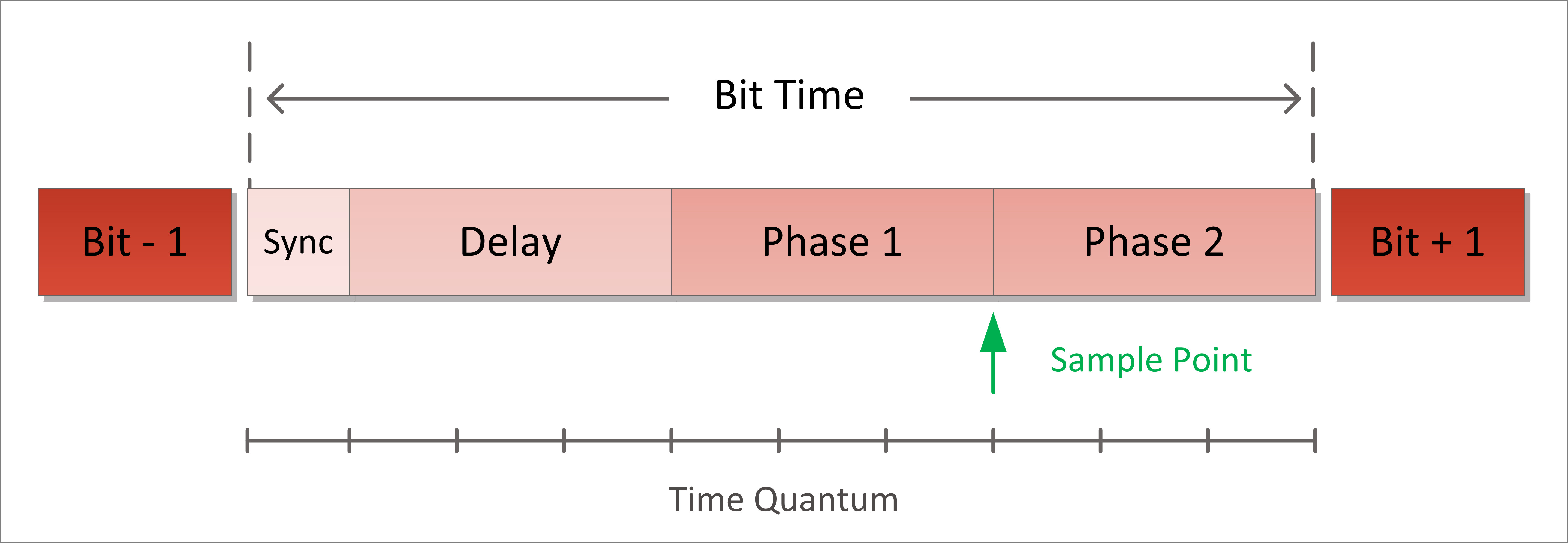
[Figure 2 | CAN bit timing]
The scanning time can be determined with the help of various processes, including with the process according to patent DE102009039200 A1.
For CAN FD, a significantly higher level of precision in frame generation and an adjustment of the signal generation for the measuring of both scanning times of all possible frame types is required (CAN/CAN FD, standard/extended, ISO/non-ISO).
Hardware
The type and scope of the control unit tests to be carried out determine the required hardware resources.
The individual communication parameters must be moved to the limits of the permissible tolerance range and beyond it in order to be able to determine the safety and error tolerance of the communication with a control unit.
Restbus controller
The communications matrix for CAN or CAN FD can be optionally defined in the DBC, FIBEX or AUTOSAR system description formats. The restbus controller of the GÖPEL electronic platform Series 61 has a modular and therefore scalable test resources concept. This makes flexible adjustment to the respective test object possible.
For CAN FD communication a TJA1044GT transceiver is used in combination with the integrated BOSCH CAN FD IP core and allows a bitrate of up to 10 Mbit/s. The functionalities for restbus simulation (frame-based or as per AUTOSAR), transportation and diagnosis logs or network management were correspondingly expanded for CAN FD.
Stress, trigger, and analysis module
Using the stress, trigger and analysis module Basic CON 4055 the CAN/CAN FD communication can be specifically manipulated and analysed. This creates the opportunity to carry out precise log tests. The Basic CON 4055 can disrupt any CAN/CAN FD messages and has more than 250 independent message triggers for this on four configurable ports as well as trigger input and output for the use of external resources.
The analysis functionality also includes bitrate measurement for CAN/CAN FD communication. In the case of CAN FD, there is the option to measure both bitrates at the same time (arbitration and data phase).
The module is used in the current interface and network testers.
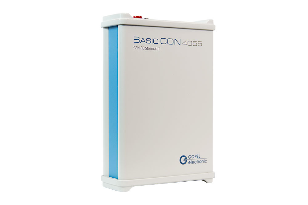
[Figure 3 | BasicCON 4055 stress and trigger module]
Signal generator
The determination of the scanning time touches upon error handling in the data link layer in the process according to DE102009039200 A1. The sender used here must be in a position to generate modified CAN/CAN FD messages. The manipulation of the message takes place via a partial inversion of an individual bit in the data area.

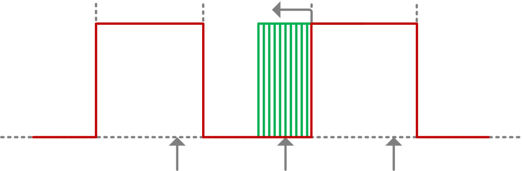
[Figure 4 | Illustration of the principle of scanning time determination]
The CAN/CAN FD participant then reacts to recognised CRC errors with an error telegram.
In order to carry out the determination at precisely one percent, a signal generator is used, which can send the test signal in a corresponding resolution, precision and speed.
Summary
For CAN FD, a large part of the test specifications of car manufacturers are still valid without restriction. In some test cases upgrades are required, others are completely newly added. The existing test systems are to be adapted and upgraded both in the hardware and software area. In hardware, this mainly affects the restbus controllers and stress and trigger modules and, in software, the complete integration of the CAN FD log.

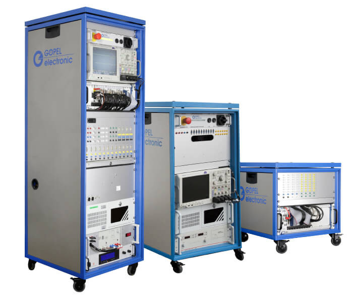
[Figure 5 | Examples of CAN/FD, LIN, Flexray, Ethernet network test systems]


