
Build a connected open door alert system with XBee
December 08, 2017

You have a five-year-old son who has grown tall enough to open the door to your home office, which is packed with all your super fun gizmos. Let's disappoint that five year old.
Imagine this: You have a five-year-old son who has grown tall enough and smart enough to open the door to your home office, which is packed with all your super fun gizmos and trinkets. It has a lock, but being the lackadaisical creature you are, you forget to lock it. You’ll only be gone for a minute or two, after all!
Well, that's just enough time for your son to sneak in, rip all the jumper wires from your breadboard, find a permanent marker, and, well, you know how this ends.
In this (oddly specific) example project we’re going to build an Internet-connected SMS door alert system to prevent such disasters. The wireless system will send a text message every time the door is opened so we can rush to the scene of the future crime.
The project requires:
- Two XBee Pro S1 radios (OP-XBEERADIO)
- A Sparkfun XBee Explorer USB board
- A TS-7553-V2 single board computer
- A magnetic door/window switch
- 3.7 VDC 1 Ah lithium polymer battery
- Jumper wires and a breadboard for prototyping
- PCB etching
- 3D printing
Before we begin you should be familiar with how to connect XBee radios. If you're not, check out the guide "A friendly introduction to XBee.”
This guide is applicable to any single board computer (SBC) or computer that has an XBee radio socket. It can also be expanded on using all sorts of sensors.
Okay! Let’s disappoint a five year old!
Lay of the land
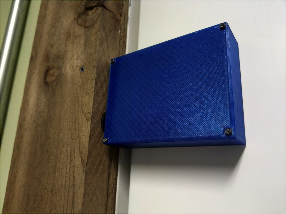
We’re after a simple solution that doesn’t take a lot of time, but also looks good when finished. This means we’ll want to have a nice looking enclosure to mount to the back of the door and no external wires if we can help it.
The sensor is easy. We’ll just use a cheap magnetic door switch (a reed switch). For communication, the TS-7553-V2 is an XBee-ready single board computer that will act very nicely as a wireless gateway that sends alerts over the Internet.
XBee radios are small, require very little power, and are easy to use. This means we can easily mount a small enclosure on our door and power it using a battery. Excellent! We’re now ready to start our proof of concept by getting the two XBee radios to talk to each other.
Pro Tip: As mentioned in the friendly introductory guide, save yourself headaches and label your XBee radios in order to tell them apart. A piece of tape or tiny post-it note and permanent marker will do just fine. Label one with “C”, for “Coordinator” and the other with “ED”, for “End Device”. You could also write the MY 16-bit source address for extra clarity.
Buzzing XBee radios
There are two XBee radios in this project. One will be configured as a coordinator and the other as an end device. The coordinator will be installed on the TS-7553-V2 and the end device will be in the door sensor enclosure. The end device will need to communicate to the coordinator when the door is open, and the coordinator will need to listen for this communication and execute a print_data() function that will later become our send_alert() function.
Here’s how we set up the two radios.
End device configuration
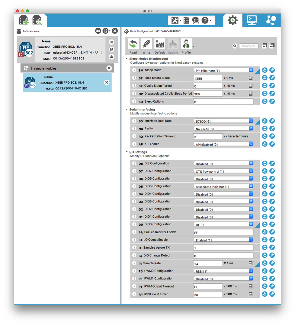
As mentioned, the end device will be responsible for transmitting data to the coordinator when the door is opened. Since it’s connected to a battery, it needs to be in a low power mode. Looking through the XBee manual, pin hibernate mode is perfect, requiring < 10 µA. We can hook up the magnetic door sensor in such a way that hibernate mode will be active when the door is shut and inactive when the door opens.
Next we need to let the coordinator know when the door opens, so we’re going to send a periodic signal. XBee provides a method for transmitting all input signals every 20 ms, which is perfect (IR). We’ll also want to configure at least one DIO as input. Let’s pick on DIO0 (D0) and configure it as a digital input. It doesn’t much matter what the input is, but since it makes sense to read “True” in a script when the door is open, let’s just tie it to 3.3 VDC.
To recap:
- Use hibernate pin connected to magnetic door sensor (SM = 1)
- Send periodic input signal readings (IR = 0x14)
- Use DIO0 as input signal, tied to 3.3 VDC (D0 = 3)
Coordinator configuration
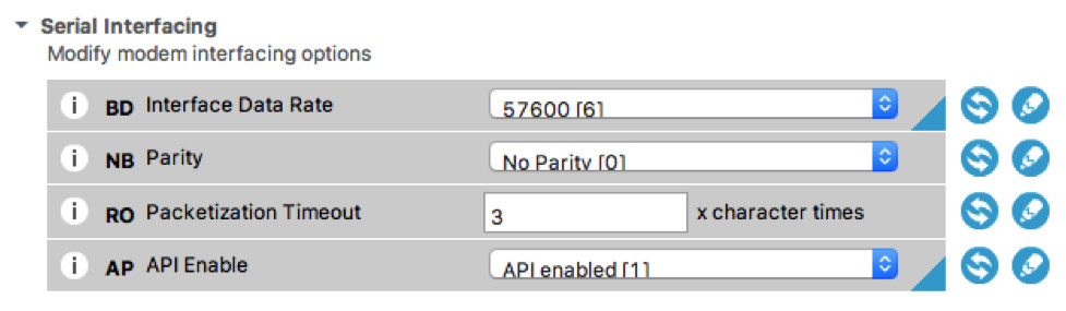
 The only thing we need to do with the coordinator is enable the serial interfacing API operation. This is so we can use data API frames in our script later on.
To recap:
- Enable the serial interfacing API operation (AP = 1)
Pro Tip: Since this will be connected to the TS-7553-V2, we will need to cut or bend pin 8 to avoid some hardware conflicts (to be fixed in a later revision).
Circuit design work
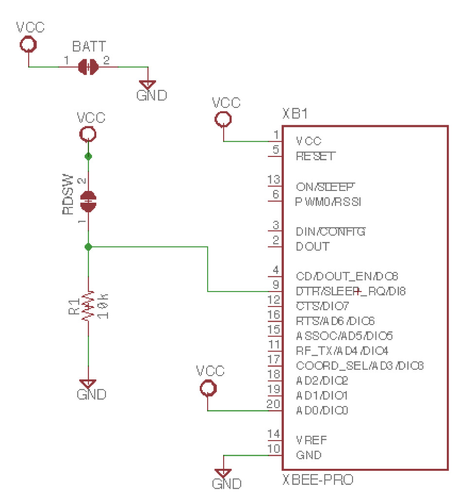
 There are two main points of interest here. One is to put the radio to sleep when the door is shut and the other is to tie DIO0 to 3.3 VDC. The rest is to simply power the radio (3.3 VDC and GND). It should be a fairly simple schematic.
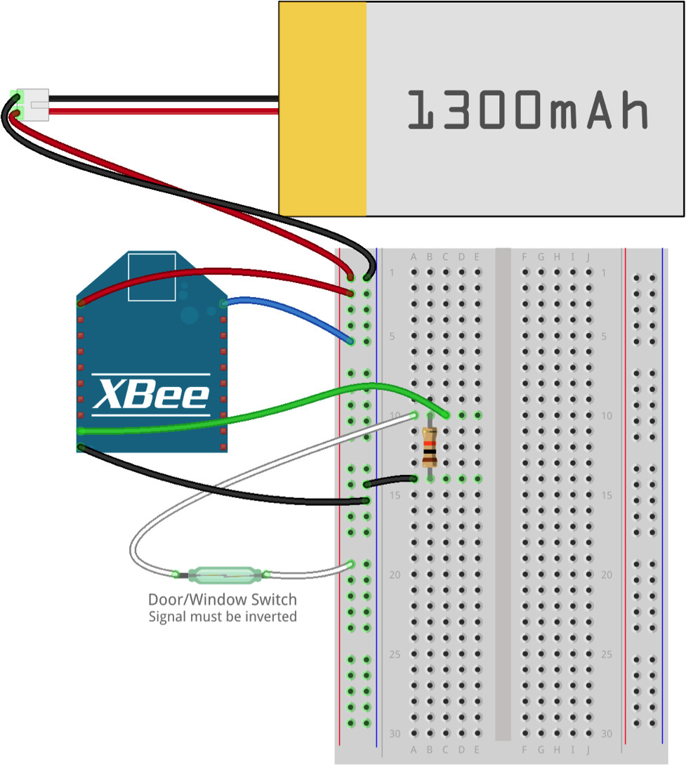
Let’s use Eagle CAD software for the schematic and PCB design (later). The schematic is available in the resources directory of the embeddedarm/xbee-door-alert repository. For now, you can take the pictured schematic and translate it to a breadboard.
 Sleep mode is enabled when
 SLEEP_RQ is floating or high and disabled when low. The magnetic door sensor, or reed switch, is connected when the door is opened. This means we’re going to need to use a pull down resistor so that sleep mode is disabled when the reed switch is connected (door opened) and enabled when the reed switch is open (door closed). This is the most complicated part of the circuit, so have no fear! The rest is self explanatory.
Naturally, there are opportunities for improvement. For example, the battery is supplying a full 3.7 VDC and will drop below 3.3 VDC as it starts to drain. To properly power this circuit we should have a buck regulator like the TPS61200 between the battery and the XBee radio. Furthermore, we should be able to easily recharge the battery without needing to open the enclosure each time, so recharging circuitry like the MCP73831T should be added and brought out to a micro USB header. Other improvements could include a status LED and MMS-110-01-L-SV XBee socket connectors.
All of these improvements require more glue logic/components, and are well beyond the scope of this project. For now, we just want it to work. Even without the regulator, at < 10 µA using a 1000 mAH battery we should have plenty of life between charges.
With this out of the way, we’re ready for prototyping and software.
Scripting the TS-7553-V2 for listening
 We’re going to use Python since it’s such an easy language to grasp and offers so much in terms of third party libraries. In particular, the
 blalor/python-xbee library, which has several example scripts to start from, will make very quick work of the XBee communication portion of our script. We’ll also be sending out an email or SMS text message whenever the door is opened, which will be made easy by the standard smtplib library .
All we need is to initialize our XBee socket and serial port, listen for data, and then send the alert via email to a specified address. To make this easy, we’ll use Gmail’s SMTP server instead of setting up the TS-7553-V2 as an email server. The specified address can be a traditional email address or an SMS/MMS email gateway provided by your wireless carrier. For example, if your number is 555-123-4567 and your provider is Verizon, you could send an email to [email protected]. Here’s a (non exhaustive) list of gateways for convenience.
Let’s start simple and see if we can receive data from the XBee end device and print it to the terminal. Here’s the script that will do that:
import serial, os, time
from xbee import XBee

# Need to be sure to reset the XBee radio socket before starting
# Specific to TS-7553-V2.  May not be required on other systems.
os.system("echo 0 > /sys/class/leds/en-xbee-3v3/brightness")
os.system("echo 1 > /sys/class/leds/en-xbee-3v3/brightness")

# Device name ttymxc7 is specific to TS-7553-V2. Refer to your
# boards manual.
serial_port = serial.Serial('/dev/ttymxc7', 57600)

def print_data(data):
    """
    This method is called whenever data is received
    from the associated XBee device. Its first and
    only argument is the data contained within the
    frame.
    """
    print data

xbee = XBee(serial_port, callback=print_data)

while True:
    try:
        time.sleep(0.001)
    except KeyboardInterrupt:
        break

xbee.halt()
serial_port.close()
When we run this script using python xbee-door-alert.py we should see an output similar to the one below when our reed switch is disconnected or the door is opened:
root@ts-imx6ul:~# python xbee-door-alert.py
{'rssi': "'", 'source_addr': '\xbe\xef', 'id': 'rx_io_data', 'samples': [{'dio-0': True}], 'options': '\x00'}
...
What we’re interested in is seeing the value of dio-0 in the samples array. Since it’s value is True, we know the XBee is awake and transmitting data successfully!
The next step is to get email working. Mainly, this requires creating a new send_alert() function and changing the callback from print_data to send_alert. The send_alert() function looks like this:
def send_alert():
# For security, let's grab credentials from a config file.
# Copy config.example.ini to config.ini with your info.
config = ConfigParser.ConfigParser()
config.read("config.ini")
gmail_user = config.get('Credentials', 'Username')
gmail_password = config.get('Credentials', 'Password')
to_email = config.get('Email', 'to')
try:
server = smtplib.SMTP_SSL('smtp.gmail.com', 465)
server.ehlo()
server.login(gmail_user, gmail_password)
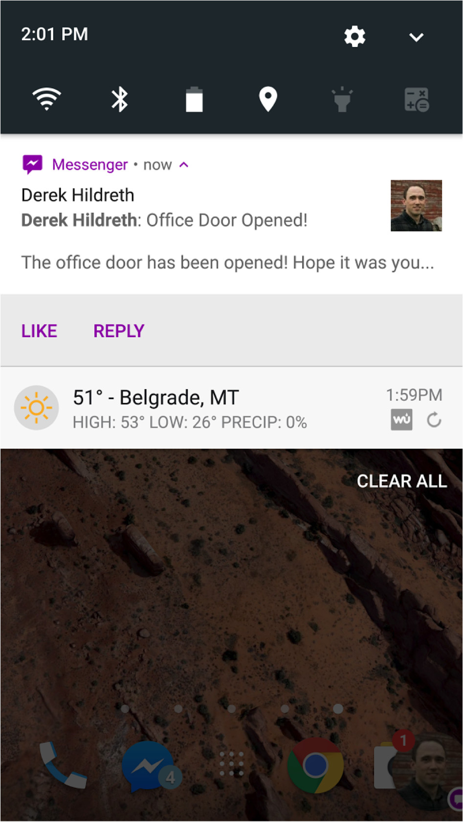
msg = MIMEText("The office door has been opened! Hope it was you...")
msg['Subject'] = "Office Door Opened!"
msg['From'] = gmail_user
msg['To'] = to_email
server.sendmail(gmail_user, [to_email], msg.as_string())
server.close()
print "Alert email sent!"
except:
print "Something went wrong in send_alert()!"
print sys.exc_info()[0]
raise
For full context, please see the example source code published on GitHub in the embeddedarm/xbee-door-alert repository. Example system init scripts for running the script on startup are also included in that repository.
And, that’s it! Our email configurations are saved in a file called config.ini that makes it easy to customize and secure to keep in a public github repository. You’ll want to set it up with your own email information and test to make sure it works. If all goes right, you’ll get an email or SMS text message alert on your phone!
 Next, let’s work on getting a prototype built so we can install our solution! If you’re just here for the introduction of getting XBee radios to communicate with one another, you can stop here. If you’re the sort of person who enjoys the making process, then look out for part two! We’ll be playing with homemade PCBs and a 3D printed enclosure to put everything in.
Derek Hildreth is eBusiness Manager at Technologic Systems. Prior to his current role, Derek was an Applications Engineer for Oracle and Embedded Systems Engineer at Technologic Systems.
Technologic Systems
LinkedIn: www.linkedin.com/company/technologic-systems
Facebook: www.facebook.com/embeddedARM
YouTube: www.youtube.com/user/embeddedarm
GitHub: github.com/embeddedarm


