
Managing SoC complexity with scenario model verification
May 01, 2014

Graph-based scenario models assist engineers with project management, thorough verification, and other aspects of complex SoC development.
Developing a System-on-Chip (SoC) requires managing many complex aspects of design. The sheer number of transistors is overwhelming, but complexity is not just about quantity. An SoC contains highly sophisticated features with precise functional specifications and an array of requirements. In addition to the complexity of the design, verification that the each of the features and the entire SoC meet their specifications and requirements is also a huge challenge.
Beyond design and verification complexity, project management of the overall process is daunting. No single solution can address all, or even most, aspects of SoC complexity. However, some techniques can tackle specific parts of the problem such as with graph-based scenario models, a formalism that directly reduces verification complexity while providing side benefits for managing SoC design and project complexity.
SoC verification
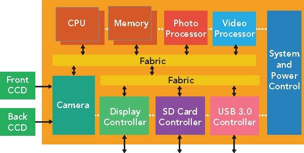
The role of graph-based scenario models can be illustrated in the context of an example digital camera SoC design (Figure 1). The raw image is captured from a Charge-Coupled Device (CCD) array (front or back) by the camera block. It can be displayed for the user, manipulated by the photo processor, transmitted via a USB port, or saved to an SD card. A series of such images may be treated as a video stream and handled similarly by the video processor and the other Intellectual Property (IP) blocks in the SoC.
|
|
The SoC has intertwined data flows and supports some parallelism. With two embedded CPUs, it's possible to simultaneously program multiple IP blocks. Further, if the fabric has crossbar capabilities, multiple data flows can run in parallel between different IP blocks and memory, or directly between IP blocks if a memory buffer is not needed. Verification requires that all these possible flows be exercised, in parallel when the architecture supports it, in ways that mimic the actual end use in the camera.
The verification team must understand all of the data flows and all possible interactions if it is to develop a testbench environment. Treating an SoC purely as a black box does not provide adequate verification; it's hard to stimulate deep behavior in a large design strictly by manipulating the inputs. Thus, SoC verification teams almost always develop C tests to run on embedded processors as part of their methodology. Of course, hand-writing tests is also difficult, and it's virtually impossible to hand-write tests for multiple processors that coordinate with each other and the testbench to fully exercise the SoC.
Graph-based scenario models
The verification team faces a challenge in understanding all the possible behavior and data flows within the chip. A paper specification is hard to digest and subject to all the imprecision of a natural language. Attempts to describe a full SoC using purely formal methods have been unsuccessful due to the description's complexity and the fact that not all design types are a good fit for declarative languages.
One method gaining acceptance is the graph-based scenario model. Such a model is a formalism – a directed graph – but does not require a formal language. It can be described using the standard C/C++ language plus a few constructs from the standard Backus-Naur Form (BNF) notation. The graph shows interconnections and legal data flows among IP blocks in the SoC. A scenario model looks like the data flow diagram that an SoC architect might draw on the board, except that it is drawn with outputs and outcomes on the left and inputs on the right.
As shown in Figure 2, possible end-user scenarios include:
- A raw image read from one of the CCD arrays and displayed on the screen, written to the SD card, or sent out the USB port
- A raw image read from one of the CCD arrays, encoded to JPEG by the photo processor, and written to the SD card or sent out the USB port
- A series of raw images read from one of the CCD arrays, encoded to MPEG by the video processor, and written to the SD card or sent out the USB port
- A raw image read from the SD card or USB port and displayed on the screen, written to the SD card or sent out the USB port
- A JPEG image read from the SD card or USB port, decoded by the photo processor, and displayed on the screen, written to the SD card or sent out the USB port
- An MPEG stream read from the SD card or USB port, decoded by the video processor, and displayed on the screen, written to the SD card or sent out the USB port
|
|

Because scenario models are hierarchical, each graph node (goal) in Figure 2 can be expanded to show details of the corresponding IP block design. The model can be developed top-down by the SoC team or bottom-up by the IP developers. Top-down development is more common since projects usually start using scenario models to address full-chip SoC verification. This may require some involvement from IP developers to fill in lower-level details. If a project fully embraces the methodology, then scenario models are also used to verify individual IP blocks and then combined into a full-chip model.
The scenario model provides insight into the SoC design and the verification space that must be covered before the chip is fabricated. This addresses verification complexity by helping define the test plan. The scenario model also helps to address design complexity since it is much like an expanded version of a data flow diagram that the chip architect might draw to explain how the design works. Thus, the graph becomes a common model that can be used among architects, designers, verification engineers, embedded programmers, and the bring-up team. This reduces project management complexity as well, both within a single project and across multiple projects that share parts of the design.
Automation with scenario models
Perhaps the greatest value of a graph-scenario model is that it can be used to generate C test cases to run on embedded processors in simulation, In-Circuit Emulation (ICE), Field Programmable Gate Array (FPGA) prototypes, or the SoC silicon in the bring-up lab. A generator walks through the graph from left to right, from desired results to inputs, assembling a series of steps that work back to the set of input values required to produce a particular outcome. Graph decision points and data values are randomized so that each walkthrough produces a unique test case. This automation eliminates the need to hand-write tests at any stage of the SoC project, from simulation all the way to the lab. Users report that they can achieve better, automated results using 20 percent of the team formerly used to hand-write tests, freeing the remainder to work on applications and other revenue-generating software.
Constraints can be added to graph to block paths that are illegal according to the specification, wall off portions of the design not yet ready to be verified, or bias the test case generation in certain directions. For example, the graph shown in Figure 2 allows the scenario of a raw image being read from the SD card, processed by the photo processor, and then displayed on the screen. This is an unnecessary step because a raw image can be displayed directly; the user can easily add a constraint that only JPEG-encoded images are sent to the photo processor to eliminate unnecessary tests.
Generated test cases are multi-threaded and multi-processor, with all communication across threads, processors, and the test bench built in. The goal is to stress test the SoC with the maximum amount of traffic and parallelism allowed. In the camera SoC, it might be possible for a camera image to be written to the USB port at the same time that a previous image is read from the SD card and displayed on the screen. This level of activity is unlikely to occur with hand-written C tests or a traditional simulation testbench and therefore provides a more complete verification of the design.
Putting it all together
As with any automatic test generation approach, the SoC team needs a way to assess the thoroughness of the verification and determine when to tape out. In addition to capturing the design and the verification space, the scenario model also serves as the system-level coverage model. Because of the definitive nature of walking through the graph, verification engineers know at test-case generation time precisely which end-user scenarios (paths) and goals in the graph have been covered. They don't need to collect and consolidate run-time coverage to assess verification progress. More importantly, they can avoid spending weeks running additional simulation tests that add little if anything to coverage results.
Scenario models and automatic test case generation form a closed-loop coverage system. A verification engineer can point to any uncovered path or goal and the generator will produce a test case that will cover it. The same applies to cross-coverage spanning paths or goals. The TrekSoC family of products from Breker provides closed-loop coverage and the other benefits of scenario models.
Graph-based scenario models capture critical design and verification knowledge, enable better communication among SoC project team members via common models, reduce manual effort at multiple points in the process, accelerate the schedule, and verify the design more completely to increase the chances for first-silicon success.
Breker Verification Systems, Inc.www.brekersystems.com @BrekerSystemswww.linkedin.com/company/1010418 plus.google.com/107630306780826149597/posts www.youtube.com/user/BrekerSystems


