
Getting started with the WeMos D1 Mini ESP8266 Dev Board
June 16, 2017
Blog
[D1 Mini front by Tpkull WeMos via Wikimedia Commons, CC BY-SA 4.0.] Since Arduino boards have become something of a de facto standard for maker and DIY projects, many other boards have adapted...
[D1 Mini front by Tpkull WeMos via Wikimedia Commons, CC BY-SA 4.0.]
Since Arduino boards have become something of a de facto standard for maker and DIY projects, many other boards have adapted their systems to be programmed within the Arduino IDE. One of the most interesting modules out there is the ESP8266, and I finally decided to jump on this bandwagon with a WeMos D1 Mini board. This amazing board isn’t much bigger than a quarter and includes 11 digital I/O pins as well as a single analog pin, all for a price well under $5.
The install procedure
After receiving it, my first job was to get it to a state where I could interface and program it with the Arduino IDE. As I already had the Arduino IDE installed, the next step was to download and install the Windows drivers for it from the WeMos website.

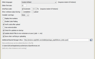
I then set up the Arduino IDE to work with the D1 Mini by entering the additional boards manager under File > Preferences and entering this link [http://arduino.esp8266.com/stable/package_esp8266com_index.json] in the “additional boards manager URLs” box. After this, I opened the boards manager under Tools > Board, and installed the ESP8266 platform. This is quite a large download, at over 153 MB as of this writing, so if you’re trying this yourself, it may take a while. After this is done, ESP boards will show up in the board menu. At this point, you’ll need to go to Sketch > Manage Libraries and search for “ESP8266” and install “ESP8266 Microgear.” When I did this, I restarted the Arduino IDE many times along the way, likely more than was necessary.
USB problems
[youtube=https://www.youtube.com/watch?v=q2k3CzT5qE0]
This process more or less followed along with the video above by YouTuber Innovative Tom. At this point I should have been able to plug my WeMos board in and happily program it like an Arduino. When plugged in though, a blinking blue light came on and I could even detect a new wireless network called “AI-Thinker_00535D,” corresponding to the unit’s WiFi Module. I then did what any normal computer experimenter would do and tried different USB ports, restarted the Arduino IDE, my computer, swapped micro USB cables, and even tried a different computer to see if it would at least acknowledge it as a USB device.
Unfortunately, none of this worked, even when I tried another WeMos board. I set it aside for a few days until I could get to my local hackerspace where I suspected there would be a few people that had dealt with these boards before. Though the people I talked to had not used these specific boards before, they were generally familiar with the technology, and one of them tried to access it on his own computer and micro USB cable. To my pleasant surprise, this came up as a device immediately, and worked on my computer as well — using his cable. So the lesson here is to never trust cheap USB cables. I also question whether I actually swapped my own cables, since they looked nearly identical. I’ve since ordered another distinctly red cable so I have one I can easily see and hopefully trust!

Hello, World!
After that bit of yak shaving, programming the WeMos board was actually pretty easy. Along the way I downloaded “D1_mini_Examples” as a zip file from GitHub, then added it in the Arduino IDE under Sketch > Include Library > Add .Zip Library.
I was able to access it on COM8 in my Arduino IDE (which conveniently also showed up in the device manager) and selected the WeMos D1 R2 & Mini under Tools > Board. I loaded a blink sketch from the examples under File > Examples > WEMOS D1 mini Examples > Basics and uploaded it, programming the board to blink its onboard LED. I even adjusted the timing and uploaded it again to make sure it was responding to my commands properly. To make sure things were working correctly, I loaded a “Hello, World!” program from the same example dialog which output, as you might guess, “Hello, World!” on the serial monitor.
Considering the price of these boards, I’m quite happy with the results so far. On the other hand, I’m not thrilled with my USB cables. Blinking LEDs, and doing the job of a normal microprocessor is good, however, I’m really looking forward to delving into its networking capabilities. For a quick example of what they’re capable of, here’s a WeMos-enabled mailbox that can tell you when the mail has been delivered.


