Making the leap from Arduino to Raspberry Pi: Initial use experience
May 24, 2017

As mentioned in my last article, I have a decent amount of experience with Arduino boards, and quite a bit more with industrial programmable logic con...
As mentioned in my last article, I have a decent amount of experience with Arduino boards, and quite a bit more with industrial programmable logic controllers (PLCs), but until now I haven’t actually sunk my teeth into the Raspberry Pi. Now that I have one of these boards, it was time to actually give it a try.
Initial challenges: Hardware setup
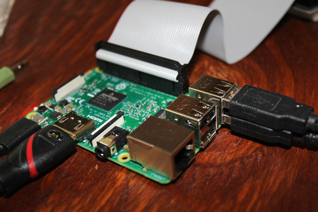
Although the Raspberry Pi 3 is impressive, with a quad-core ARM Cortex-A53 processor, WiFi/Bluetooth capabilities, and GPIO pins, what is on the board is what you get, nothing else. To get it to work as a desktop-style computer, you’ll need a few other accessories, such as a USB power supply (it’s supposed to have 2 amp capacity), monitor, and HDMI cable. I’d also recommend an inline USB switch, which I had in my parts bin, since the board doesn’t include an on/off button. Finally, you’ll need a micro SD card with an operating system (OS) installed on it. The officially supported OS is called “Raspbian,” which can be found here along with a few other options.

[Figure 1 | You’ll need a few accessories to get things working correctly.]
Especially if you’re using a Windows-based machine this is where things can get tricky, since you actually have to “burn” an image, not just copy files. Linux generally includes this capability by default, but for Windows you’ll have to use a piece of disk imaging software. For reasons I’m not entirely sure of my first install of Win32 Disk Imager didn’t agree with my system, so I downloaded it again from Source Forge and finally got it to work. There is also a “NOOBS” (New Out Of the Box Software) installer available at the same link as the Raspbian OS, which is supposed to make this process easier — perhaps I should have tried that instead.
After getting the OS installed I had to deal with the image not filling the screen due to a setting called “overscan,” as well as a few keys on the keyboard that didn’t quite seem standard. Minor difficulties, but not something that I expected in a fresh computer install.
And it’s an actual computer!
After these few difficulties my initial impression with the OS was quite good. The system seems to have a vaguely “Mac-ish” feel to it that is tough to put your finger on, but is kind of a nice change after using PCs for so long. Navigation is via keyboard and mouse, and once the screen issue was mostly mitigated it was pretty easy to log onto my home network and surf the Internet. There are quite a few programming tools loaded by default, as well and an office suite. It even includes a version of Minecraft, which could be an interesting distraction if you have some time to kill.
Though there is a fairly developed graphical user interface (GUI), it definitely helps to have some Linux or other command line background. In order to make changes, you’ll need a passing familiarity with modifying files using the “sudo” command, and you’ll likely have to restart (via unplugging or the very handy aforementioned switch) several times to get things how you want. The good news is that there is a massive amount of help available online if needed.
General purpose input/output
So yes, it’s pretty neat that you can do this for under $40, and it’s a great use for, say, a spare monitor. That being said, the really interesting feature for me is the Pi’s GPIO capabilities. Given the limited number available by default, though, I can see why people still use Arduino boards or both systems together for control.
At this point, I don’t expect to be an expert, but at least wanted to know how to switch an LED on and off. The good news is that, unlike some tutorials available online (likely for earlier OS versions), you don’t have to install or setup anything else. Just go into your command prompt and, per this tutorial, type “gpio mode 0 out” then “gpio write 0 1” to turn pin 0 (now set to output) on. Type “gpio write 0 0” to turn it off again.
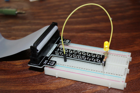
Where it gets confusing is that pin 0 is also GPIO-17, which is physically located on pin 11 on the connector. The linked tutorial gives a bit more background on this, which will likely make more sense once I’ve worked with the system further. I used a breakout board bundle from CanaKit for my experiment, which was useful to get everything on a breadboard but may or may not be necessary depending on what you have available in your parts bin.

[Figure 2 | A breakout board, like this one from CanaKit, can help you access your ‘Pi GPIO pins.]
Embarrassingly, I managed to short multiple LEDs via this breakout, giving the Pi some issues that were resolved by restarting. Be sure to use the appropriate resistor in your setup, and don’t forget that a breakout like this means you can’t just place your LED anywhere on the board!
So, there were a few trials, but I can now say that I have some limited experience with the Raspberry Pi. It seems like a great system, and I’m looking forward to using it to increase my MakerPro capabilities in the near future!
Jeremy S. Cook is a freelance tech journalist and engineering consultant with over 10 years of factory automation experience. An avid maker and experimenter, you can see some of his exploits on the Jeremy Cook’s Projects YouTube Channel!


