
Excitation current mismatch effects in three-wire RTD measurement systems, Part 1
March 16, 2015

Many medical, process control, and industrial automation applications require precision temperature measurements to accomplish their function. Resisti...
Many medical, process control, and industrial automation applications require precision temperature measurements to accomplish their function. Resistive temperature detectors (RTDs) are commonly used as the sensing element in these precision temperature measurements due to their wide temperature measurement ranges, good linearity, and excellent long-term stability and repeatability. An RTD is a sensing element made of metal with predictable resistance over temperature. The resistance of the RTD sensor can be calculated by injecting a current through the RTD and measuring the voltage. The RTD temperature can then be calculated based on the relationship between the RTD resistance and temperature.
Part 1 of this three-part article discusses the principles and advantages of ratiometric three-wire measurement systems. In Part 2 we compare the effects of excitation current source mismatch to other error sources. In Part 3 we provide solutions to minimize or reduce the effects of the excitation mismatch.
Pt100 RTD overview
The Pt100 RTD is a platinum-based RTD sensor offering excellent performance over wide temperature ranges. Platinum is a noble metal and features the highest resistivity of commonly used RTD materials enabling small sensor sizes. RTD sensors made of platinum are occasionally referred to as platinum-resistance thermometers, or PRTs. The Pt100 RTD has an impedance of 100 Ω at 0 °C and roughly 0.385 Ω of resistance change per 1 °C change in temperature. At the extremes of the usable temperature range, the resistance is 18.51 Ω at -200 °C and 390.48 Ω at 850 °C. Higher-valued resistance sensors, such as Pt1000 or Pt5000, can be used for increased sensitivity and resolution.
The Callendar Van-Dusen (CVD) equations define the resistance characteristics of RTDs versus temperature (T) in degrees Celsius. For positive temperatures, the CVD equation is a second-order polynomial as shown in equation (1). For negative temperatures, the CVD equation expands to a fourth-order polynomial shown in equation (2).
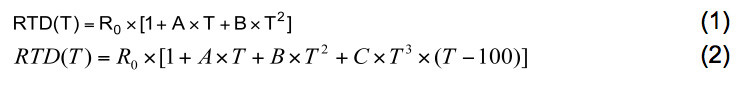
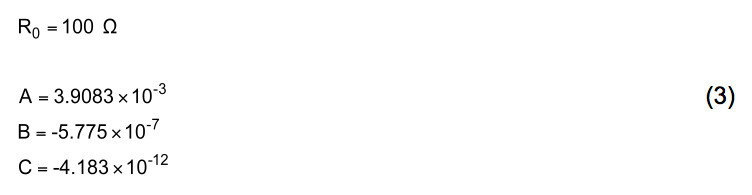
The CVD coefficients (A, B, and C) are defined in the European IEC-60751 standard. The coefficients values are shown in equation (3). R0 is the resistance of the RTD at 0 °C.
The change in resistance of a Pt100 RTD from –200 °C to 850 °C is plotted in Figure 1.
|
|

Three-wire RTDs
Three-wire RTD configurations are popular due to their balance between cost and accuracy. In the three-wire configuration being proposed, one excitation current (I1) produces a voltage potential across the RTD element. At the same time, a second excitation current (I2) is injected to cancel the resistances of the RTD leads (RLEAD) from the final measurement shown in Figure 2 and equations (4-7).
|
|

RTD measurement circuit configurations
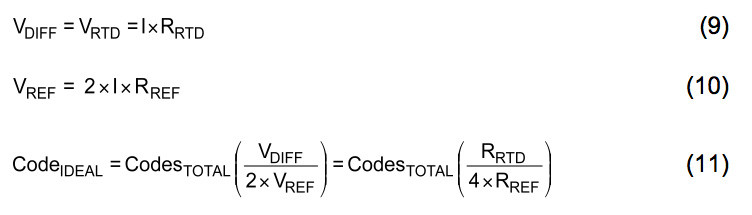
The differential RTD voltage, VDIFF, is typically converted by an analog-to-digital converter (ADC) and sent to a processor to be interpreted. The ADC compares the input voltage to a reference voltage, VREF, to produce a digital output. A three-wire RTD measurement circuit using a discrete external reference voltage is shown in Figure 3. Equation (8) defines the final conversion result based on the total number of digital codes, RTD resistance, excitation current magnitude, and reference voltage. This example assumes that the ADC has a full-scale range of ±VREF. As shown, errors due to the magnitude, noise, and temperature drift of the reference voltage and excitation currents directly result in conversion errors.

|
|

Placing the RTD and ADC in a ratiometric configuration (Figure 4), is a more accurate circuit configuration for three-wire RTD systems. In a ratiometric configuration, the excitation current that flows through the RTD returns to ground through a low-side reference resistor, RREF. The voltage potential developed across RREF, VREF, is provided to the ADC’s positive and negative reference pins (REFP and REFN).
The voltage drop across the RTD and RREF resistors is produced by the same excitation currents (equations 9 and 10). Changes in the excitation currents are, therefore, reflected in both the RTD differential and reference voltages. Since the ADC output code is a relationship between the input and reference voltages, the final conversion result reduces to a ratio of the RTD and RREF resistances and does not depend on the values of the reference voltage or excitation current (equation 11). Therefore, inaccuracies due to the magnitude, temperature drift, and noise of the excitation currents cancel, if they are perfectly matched without affecting the final conversion result. The ratiometric configuration also helps reduce the effects of external noise that appears common to both the inputs and reference because it also cancels.
|
|

Excitation current source mismatch error
The two excitation currents must be equal to each other in order to achieve the ideal transfer function (equation 11). Excitation current mismatch changes the ideal system transfer function as it lessens the effectiveness of lead-resistance cancellation.
The worst effects on the transfer function occur when one excitation current is reduced or increased by the maximum mismatch specification. This is defined in equation (12) where Δ is the excitation current mismatch.

The mismatch of I2 causes the ideal transfer function to change (equation 13).

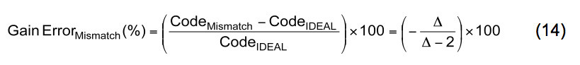
Equation (14) calculates the gain error caused by the excitation current mismatch by comparing the result of equation (13) to the ideal transfer function from equation (11).
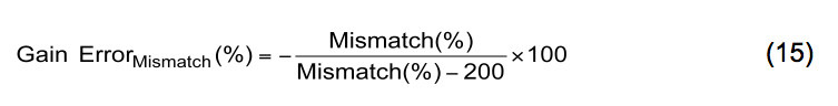
If the excitation current mismatch is specified in %FSR, the gain error can be calculated as shown in equation (15).
The gain error caused by the excitation current mismatch can be removed through a standard gain calibration. However, the excitation current mismatch typically drifts over temperature, which would require complex calibration to correct.
Summary
In Part 1 of this article we introduced three-wire RTDs, lead resistance cancellation, and the benefits of constructing a ratiometric three-wire RTD system. We showed that while a ratiometric RTD configuration removes the errors from the initial accuracy of the excitation currents, mismatch between the two excitation currents still causes a gain error.
Join us for Part 2 where we will provide an analysis of a modern ratiometric three-wire RTD measurement system to describe the sources of error, including the effects of the excitation current mismatch and drift.
References
1. Download these datasheets: ADS1200, ADS1237 and ADS1248
2. TI reference designs: TIPD120, TIPD154, TIPD152 and TIDA165
3. Check out TI’s E2E community Precision Hub blog where you can search for related topics, including this one.


