
Choosing between open- and closed-loop MIMO in BTS systems
May 01, 2009
Story

MIMO promises high-speed data rates to the designers who use the correct techniques.
While theoretical limits to Multiple Input Multiple Output (MIMO) open- and closed-loop techniques have been covered extensively in academic literature, little information is available on the associated circuit implementation complexity. Lekun examines the complexity and performance trade-offs involved in these techniques and recommends guidelines for practical system implementations.
MIMO is a promising technique for achieving the high-speed data rate needed in future wireless data systems. Multiple streams can be transmitted using MIMO, thereby increasing system throughput. Sometimes Single Input Multiple Output (SIMO) and Multiple Input Single Output (MISO) are also loosely called MIMO. Single Input Single Output (SISO), SIMO, MISO, and MIMO antenna configurations are shown in Figure 1. Currently, MIMO has been adopted by most 3G and 4G wireless standards such as WiMAX, Time Division Synchronous Code-Division Multiple Access (TD-SCDMA), and Long-Term Evolution (LTE).
|
|

In a traditional wireless system, the receiver and transmitter do not communicate back and forth. The receiver is alone in figuring out the channel information and decoding the streams. This puts a heavy complexity burden on the receiver and prevents the system from fully utilizing channel diversity or capacity. These systems are called open-loop systems.
Most current wireless standards allocate a limited feedback channel between the handset and Base Transceiver Station (BTS). This channel can be used for many purposes, especially for sending vital information about the channel back to the BTS. The information enables simple spatial diversity and multiplexing techniques that increase the system’s effective Signal-to-Noise Ratio (SNR) and potentially simplify the receiver architecture. These systems are called closed-loop systems.
Open-loop MIMO
For a SIMO system, the receiver combines data streams from multiple transmit antennas using maximum ratio combining methods to achieve diversity gain. For multiple transmit antennas, the channel becomes more complicated, and there is interference between different transmitted streams. If the transmitter has no channel knowledge, the receiver is alone in exploiting MIMO capacity, which usually means that a complicated algorithm is required.
Spatial multiplexing
Spatial multiplexing is a well-known open-loop MIMO technique widely used in wireless systems. Different data streams are sent via each transmit antenna. The 2x2 spatial multiplexing system depicted in Figure 2 can be modeled as shown in Equation 1.
|
|

|
|
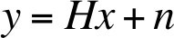
In this equation, x is the transmitted signal vector, H is the channel matrix, n is the adding noise vector, and y is the received signal vector. The straightforward way to estimate the transmitted signal x from received signal y is to multiply y with an inverse channel matrix, such as zero forcing or minimum mean squared error. However, this is not optimal detection.
Optimal detection can be achieved with Maximum Likelihood (ML) criterion. In most cases, ML can be implemented by finding the transmitted signal vector that minimizes the Euclidean distance with respect to the received signal vector y, as shown in Equation 2.
|
|

Unfortunately, ML’s computational complexity is exponential with the number of transmit antennas and possible constellation points, which makes it unsuitable for practical purposes.
A widely used suboptimum ML solution is sphere decoding. The principle of the sphere decoding algorithm is to search the closest lattice point to the received signal within a sphere radius, where each code word is represented by a lattice point in a lattice field. Sphere decoding significantly reduces detection complexity, whereby its performance is comparable to ML detection. However, even though sphere decoding can reduce complexity, it is not suitable for implementing a large number of antennas and high modulation rates such as 64 quadrature amplitude modulation.
Space-time codes
Another widely used open-loop MIMO technique is space-time code. With space-time codes, a single data stream is transmitted from multiple transmit antennas, but the signal is coded to exploit independent fading in multiple antennas to achieve space diversity.
The most popular space-time code is Alamouti (Figure 3), which is adopted by many wireless standards. Typical Alamouti code is expressed in Equation 3 and rearranged in Equation 4.
|
|

|
|

|
|
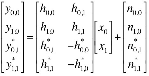
Equation 4 implies that signal x0 and x1 are transmitted in two orthogonal paths. Therefore, x0 and x1 can be detected independently, and only simple linear processing is required.
Compared with spatial multiplexing, using Alamouti code provides higher diversity gain and does not require complicated receiver detection. However, Alamouti code transmits only a single stream instead of multiple streams. While spatial multiplexing targets spatial multiplexing gain, space-time code targets diversity gain. To compare the two schemes, consider the channel condition. One scheme is superior to another only in a specified channel condition. Many wireless standards adopt both schemes.
Given this information, how do designers switch between the two schemes to achieve optimal performance? R.W. Heath, Jr. and A.J. Paulraj propose one criterion for choosing between diversity gain or multiplexing gain: Select the scheme with minimum Euclidean distance at the receiver[1]. This method requires exhaustive searching and thus is not suitable for practical implementation. To solve this problem, Heath and Paulraj suggest using the Demmel condition number to make the selection. For a large Demmel condition number, the channel is more likely to be singular; therefore, space-time code should be chosen.
Closed-loop MIMO
Closed-loop MIMO is becoming more important in modern wireless communications. The BTS transmitter utilizes channel information to enable simple spatial diversity or beam-forming techniques that increase the system’s effective SNR and potentially simplify the receiver architecture.
For example, consider a closed-loop MIMO system with two transmitter antennas and two receiver antennas. With perfect knowledge of channel H, the transmitter can achieve an optimal transmission scheme as shown in Equation 5.
|
|
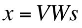
In this equation, x is the 2x1 transmitted signal vector, s is the 2x1 information vector, V is the right side unitary matrix in the singular value decomposition of H, and W is the water-filling matrix as shown in Equation 6 with α2 + β2 = 1.
|
|

With unitary matrix V, channel H is separated into two orthogonal paths. Using a water-filling matrix to allocate more power to the stream with the larger SNR can achieve maximum capacity. It should be noted that setting α = 1 and β = 1 means that all power is put to the path with the larger SNR and only one signal stream is transmitted, thus creating the maximum SNR solution.
Here, the main problem is how to obtain channel knowledge at the transmitter. Most current wireless standards allocate a feedback channel to transmit channel knowledge to the BTS. This feedback solution can work in Frequency-Division Duplex (FDD) and Time-Division Duplex (TDD) systems. Because the redundant channel information puts heavy overhead on the system uplink, channel information is usually quantized to reduce the feedback message size. This quantized information feedback is called limited feedback.
In WiMAX and LTE, the system provides a code book, which includes precoding matrices corresponding to possible channels. According to the estimated channel in the handset, the corresponding precoding matrix index is chosen and transmitted back to the BTS. Channel information quantization inevitably introduces quantization errors and leads to performance loss, as discussed by P. Xia and G.B. Giannakis[2].
Another issue worth considering in a feedback solution is its delay. In a slow-fading channel, the channel condition keeps constant in multiple frames. However, in a fast-moving environment, the channel becomes fast fading, which puts major emphasis on feedback delay. If the delay is longer than the channel’s coherent time, closed-loop MIMO will suffer significant performance loss.
Another way to obtain channel information is by uplink sounding, where the handset transmits a sounding signal in the uplink. The BTS utilizes the channel’s reciprocity property to obtain downlink channel information. The advantage of uplink sounding is that it has less delay than a feedback solution and does not require a feedback channel. However, this method has some drawbacks. Uplink sounding is suitable in a TDD system, but in an FDD system, downlink and uplink use different frequency bands whose channel properties may be different. Although there are some ways to compensate for the variation, performance loss cannot be avoided. In some systems, a special channel is allocated for uplink sounding use only, which increases uplink overhead.
Weighing the pros and cons
Among open-loop MIMO techniques, spatial multiplexing pursues maximum multiplexing gain. Although this method can transmit multiple data streams in multiple transmit antennas, it requires a complicated detection algorithm in the receiver. In contrast with spatial multiplexing, Alamouti code provides simple optimal detection and can achieve maximum diversity gain, but it transmits only one data stream in multiple transmit antennas. Choosing spatial multiplexing or Alamouti code depends on the channel condition.
As opposed to open-loop MIMO approaches, closed-loop MIMO techniques utilize channel knowledge to improve SNR or capacity and simplify receiver design. Because there is a delay to receive channel information, designers should be careful when applying closed-loop MIMO in a highly mobile environment. Furthermore, closed-loop MIMO suffers performance loss due to incomplete channel knowledge in limited feedback and uplink sounding.
Each MIMO technique has advantages and disadvantages. When designing a wireless system, designers should choose an appropriate MIMO technique by considering its service type, channel condition, complexity, and delay.
References
[1] R.W. Heath, Jr. and A.J. Paulraj, “Switching between diversity and multiplexing in MIMO systems,” IEEE Transactions on Communications, Vol. 53, No. 6, pp. 962-968, June 2005.
[2] P. Xia and G.B. Giannakis, “Design and analysis of transmit-beamforming based on limited-rate feedback,” IEEE Transactions on Signal Processing, Vol. 54 No. 5, pp. 1853-1863, May 2006.
Lekun Lin is staff wireless systems architect for Integrated Device Technology (IDT), based in San Jose, California. His primary responsibilities include simulating next-generation BTS and deriving requirements for new Wideband Code-Division Multiple Access (WCDMA) and Orthogonal Frequency-Division Multiplexing (OFDM) BTS chipset opportunities. Lekun holds a PhD in Electrical Engineering from the University of Utah.
IDT
408-284-4515
[email protected]
www.idt.com


