
Analog front ends for gas sensors
July 31, 2015

Liquefied petroleum gas (LPG) is the most commonly used gas found in our homes. Leakage of LPG can be life threatening. Even in low concentrations it...
Liquefied petroleum gas (LPG) is the most commonly used gas found in our homes. Leakage of LPG can be life threatening. Even in low concentrations it can be suffocating whereas if the concentration is high enough it can lead to a fire or cause a blast. Hence, it is extremely important to monitor the LPG level in our surroundings.
Another type of gas that needs to be constantly monitored and kept within certain limits is CO2. High concentration levels can cause breathing problems and prolonged exposure can lead to death.
We can prevent gas exposure-based accidents from happening by recording and maintaining gas levels in the immediate environment. Gas sensors can play a key role to this effect by raising an alarm when the level crosses prescribed safe limits.
Advances in modern semiconductor technology have empowered us to design low-cost and low-power sensing solutions to make our homes, offices, and lives safer by keeping a check on the gas levels in our surroundings.
Every sensing system comprises a basic sensing element that measures one or more electrical parameters like resistance or capacitance, and a circuitry that measures the changes in those parameters. Most of these sensors can operate on battery power so they can work uninterrupted for years on end. Hence, it becomes imperative that they consume low power for their operation.
To pass the sensed information to the controller, analog front ends (AFE) are used. These allow the microcontroller to understand analog signals sent by sensors by converting them to a digital signal and then performing post processing on the received data.
Parameters measured by sensors
Sensors measure changes in resistance and capacitance.
Resistance
There are two common ways to measure a change in resistance: a potential divider circuit and passing a known current.
First, in a potential divider circuit, we connect a sensor whose resistance varies depending on some physical parameter like temperature, pressure, etc. We compare the changing value of the sensor to a fixed value resistance. In such a circuit, the voltage of the connecting node (ADC) of the fixed resistance and the sensor depends on the resistance of the sensor and thereby on the physical parameter being measured.
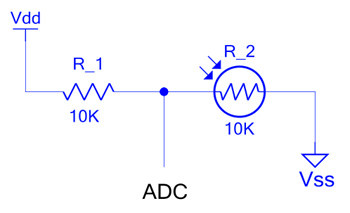
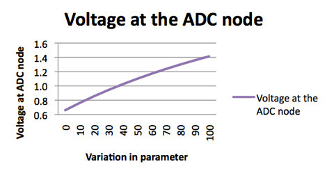
This voltage is measured using an ADC and the digital output of the ADC is used by the microcontroller. The microcontroller is programmed with an algorithm that uses the known relationship between the variation in resistance of the sensor and the physical parameter being measured to calculate the physical parameter.
Second, in passing a known current, a known current is passed through a transducer whose resistance varies with the changes in the parameter being measured. As per Ohm’s law:

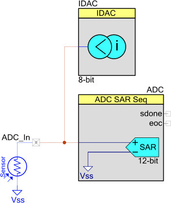
The voltage across the transducer will vary depending on the parameter being measured. This voltage can be measured using an ADC. The ADC reading can then be used to calculate this parameter.
Capacitance
There are sensors that are capacitive in nature. In these sensors, the effective capacitance of the sensor is measured to find out the value of parameter of interest. There are various ways in which a capacitor can be measured.
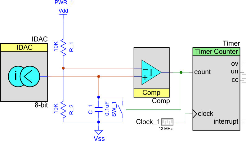
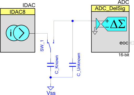
A current digital to analog converter (IDAC) charges the variable capacitor and, when the voltage at the capacitor crosses the voltage at the inverting terminal, the switch is turned on. This discharges the capacitor and the cycle repeats. During every charging and discharging cycle, the value of the counter registers are captured and processed in the firmware to calculate the capacitance value by applying the relevant mathematical equations.
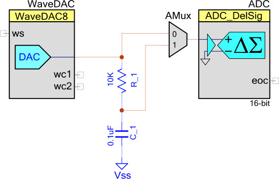
In passing a known AC signal, a known AC waveform is passed through the variable capacitor and the phase difference introduced by the capacitor is measured. The phase difference in such a circuit can be given as:
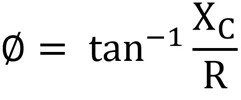
Where Xc = Capacitive reactance of capacitor for the given frequency
In charge sharing between capacitors, a known reference capacitor is charged with a known voltage, and the unknown capacitor is connected to this capacitor. Charge sharing takes place and the voltage across the capacitor drops. By measuring this drop, we can find the value of unknown capacitor using the equation:
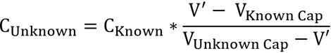
Where V’ is the potential after connecting the unknown capacitor to the known capacitor
VKnown Cap is the voltage across the known cap before connecting the unknown cap
VUnknown Cap is the voltage across the unknown cap before connecting to the known cap
Basics of gas sensors
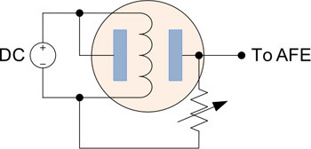
A basic GAS sensor (MQ series) consists of a heater which is heated by an AC or DC voltage source of around 5V. Once heated, it provides the required conditions for the chemical sensor built inside the sensor. The resistance of the sensor varies depending on the concentration of the gas being measured. A resistive potential divider is built using an additional resistance and the output of this potential divider is fed to the AFE, normally an ADC.
Let’s look at how we can implement a gas sensing AFE. For this example implementation, we will use a PSoC4 from Cypress Semiconductor (See application note for information on getting started: AN79953).
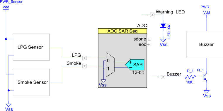
This gas sensing solution uses two different gas sensors: an LPG sensor and a smoke sensor.
The outputs of these sensors are fed to an ADC whose outputs are processed in the firmware. The ADC in a PSoC 4 yields a 12-bit result, which is further averaged with the help of ADC’s dedicated hardware averager. This averaged output of the ADC is processed in the firmware with an IIR filter (read Cypress application note AN2099 for more information on using PSoC devices for IIR filters). ADC values are compared against independent thresholds for each sensor, and whenever the ADC output of any channel crosses this threshold, the LED starts blinking to warn users. Along with this, the buzzer pin goes high, which brings the transistor Q1 into active mode. The transistor then starts driving the buzzer, giving an audible warning to alert the users.


