
Using ADASIS Version 3 for Precision Localization in Highly Automated Driving, Part 1
January 29, 2019
Story

Automated driving features will become a reality in more and more vehicles in the very near future. The underlying functions consist of sensor systems that perceive the vehicle and its surroundings.
A major prerequisite for highly automated driving systems using high-definition map data is the knowledge about the vehicle's position. This position needs to have a much higher precision than can be achieved with a GNSS sensor alone. Therefore, various other sensor systems like gyroscopes or odometers can be used to enhance the position estimation. This contribution describes a system using another input, ADASISv3 map data, to improve the positioning. The map data is received from a map database and then compared to traffic sign measurements from a camera system.
The comparison results are used to enhance the vehicle's position. The system has been evaluated with a test vehicle in real world situations. A description of the scenario and test results are included in the contribution.
Introduction
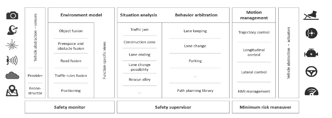
Automated driving features will become a reality in more and more vehicles in the very near future. The underlying functions consist of sensor systems that perceive the vehicle and its surroundings, a decision module following the goal of a system, and actuators to execute the decision (see Figure 1). This so-called sense-plan-act [1] path forms the basis of many modern automated driving architectures.
The perception part will use a large variety of sensors. Apart from environmental perception sensors (e.g. Lidar, Radar, camera), interoceptive sensors (e.g. wheel ticks, gyro) and localization sensors (e.g. GPS) are used to evaluate the overall situation of an automated vehicle. Each of these three sensor categories supports the calculation of position and ego-motion information for a highly automated driving (HAD) system. This information simplifies many algorithms in the perception and decision modules. However, there is no single sensor to provide a high-precision safety-rated position at a high frequency to support the system's decision or environmental perception unit. It even becomes more complicated if a system requires a global position to relate to other vehicles in a global frame or to match with global map data.
Therefore, a software component providing a highly accurate safety-rated position in a HAD system based on multiple sensor inputs is crucial to satisfy the needs of HAD applications. One possibility is to add a fourth type of “sensor”: a high definition (HD) map. This data contains information of landmarks (e.g. traffic signs, poles) that can be detected by a camera or other exteroceptive sensors and provide a second source for a global position to be fused with other data.
System Context
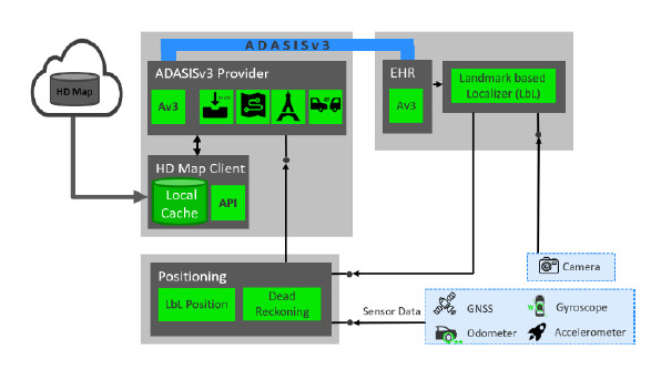
The overall system consists of three different processing components as depicted in Figure 2. The data processing starts with receiving and providing map data within the vehicle. This data is received via an online connection or can be stored locally on a hard drive. However, as HAD map data needs to be up-to-date, the online case is the more likely one. All major map providers (e.g. TomTom) offer this possibility and provide information on landmarks over a network. After receiving, the data are provided in the standardized electronic horizon format ADASISv3 (see Section 3). As there might be other systems also receiving the ADASISv3 data stream, each system needs its own ADASISv3 Reconstructor to provide an easy-to-access data structure. This data structure contains all information of the electronic horizon tree including landmarks that are needed for this system. The landmark-based localization component (LbL) then accesses the landmarks and receives exteroceptive information from a camera system. In case of a successful matching, the LbL provides absolute position updates to a third component. The positioning block combines traditional sensor inputs (e.g. gyros, odometer, GNSS) with the LbL and provides a single source of truth positioning information to all HAD system components.
Map Data in ADASIS v3 Format
Providing map data to an automated vehicle is one key enabler to improve the driving behavior and to ease algorithm design. The ADASIS Forum has specified a description format for serializing and describing map data for ADAS applications. The ADASISv2 format has been widely used in the industry for the current state of the art ADAS systems. However, this v2 format focuses on SAE L0-L2 systems only. It does not provide lane accurate map information and is missing various information needed only for higher automation levels.
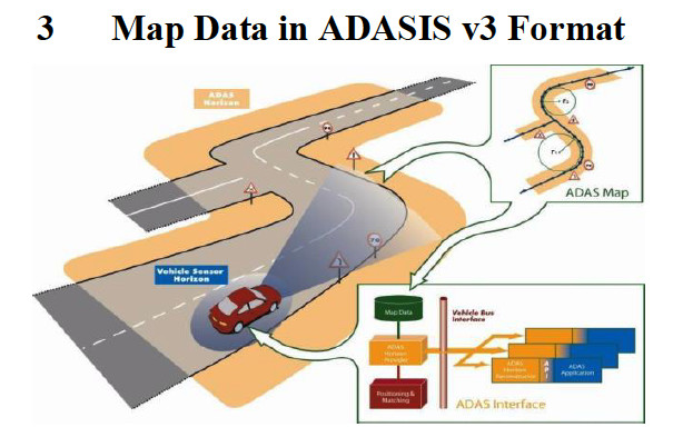
The system layout is depicted in Figure 3. An ADASISv3 provider receives the map data and the position. It then builds an electronic horizon (eHorizon) describing the vehicle's upcoming road network. This eHorizon contains all necessary information. The ADASISv3 standard describes the eHorizon as one or multiple paths. These paths contain information about the available lanes, interconnections to other paths, and so-called profiles. These profiles contain information about various different elements of a path. This starts at single event profiles (e.g. traffic signs), over slopes attached to a region, up to speed limits attached to a path. This ADASISv3 eHorizon is then serialized and sent via the vehicle network to all ADAS ECUs to be processed. This transfer can be done in a single step. However, more common is the incremental transfer. This enables the provider to only transfer an update to the ECU.
Many profiles are already defined by the ADASISv3 standard. However, it is also possible to extend the profile set by custom profiles. These profiles contain customer-specific information. For the system described in this contribution, EB extended the ADASISv3 standard by a profile containing landmark information. The showcase uses traffic signs and its geo location received from an HD map.
Landmark Based Localization
The general processing chain of the landmark-based localization is shown in Figure 4. First, the system detects traffic signs that are candidates for localization. These traffic signs do not only need to be detected, but also localized relatively to the vehicle. A common traffic sign detection system from mass production might not provide this data or may not be as accurate as needed for LbL. After detecting a traffic sign, the system will try to look up the traffic sign in an HD map. This look-up is limited based on the current location of the vehicle. As traffic signs are relocated, changed, removed, or newly placed, this look-up can result in different outcomes:
- The traffic sign is found and is non-ambiguous.
- Multiple traffic signs are found, and it cannot be decided which sign was detected.
- No sign is found in the map database.
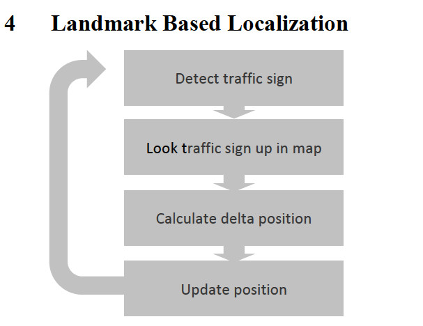
Case 1 is the case which enables the system to proceed in the chain. Case 2 and case 3 result in a non-usable detection of a traffic sign.
The delta position calculation is the main step of the LbL. To update the position afterwards, the LbL needs to calculate the position shift and the estimated accuracy of the measurement. The basic assumption of this calculation is that both the measurement M and the landmark position of the map data L are correct. The measurement needs to be transferred from a sensor coordinate system into a global position by using the vehicle's ego position E:
Mego = RotateZ(M+E)
Afterwards, the LbL can calculate the delta position ΔP by the subtraction of M and L:
ΔP = M – L
The calculation of the second part of the outcome is based on the Gaussian Error Propagation. The result is then forwarded to the position update. The process chain now starts again.
Bibliography
[1] R. R. Boyd, "A Discourse on Winning and Losing," 1976.
[2] S. A. E. International, "J3016 - Taxonomy and Definitions for Terms Related to Driving Automation Systems for On-Road Motor Vehicles," 2018.
[3] I. N. Bronstein, K. A. Semedjajew, G. Musiol and H. Mu?hlig, Taschenbuch der Mathematik, 5 ed., Thun und Frankfurt am Main: Verlag Harri Deutsch, 2001.
[4] A. D. A. S. I. S. Forum, "ADASIS v3 Protocol - Specification v3.1.0 - Release Candidate 1," 2018.


